I'll also have to measure driver impedances myself, for I've been relying on manufacturer spec sheet measurements. I'd expect them to be right, but that's also a possible source of error.
Those are not usually that off..... but to have accurate simulations you need more than just 1 number. You need the full spectrum.
You don't need these for interferometry, but once you add any crossover components you do.
Last edited:
Impedance measurements are probably the easiest of all measurements you can do. Definitely do your own!
As Allen said, if using traced ones you need to check they have valid phase data. If not you can use the phase extraction in one of Jeff's/Charlies spreadsheets to fix it.
On the measurements, when doing the tweeter (and both running together) set your measuring system to only do from say 200Hz up. You can use the spl tools to normalize the data to fill in from 200Hz down.
One other thing you can do is check the voltage at your speaker terminals. Send say a 100Hz sine wave to your woofer and put an AC voltmeter across the terminals. Adjust for a max of 2.83V (lower if you can get clean results) and then you should have a safe level for your tweeter (at least I've not had a problem when high passing at 200Hz and using this level, but I have used high powered tweeters.....)
Tony.
Probably yes. It wouldn't line up at the end if we weren't. I've noticed that some helpful sites have offered zma files that have been SPLTrace'd from Zmagnitude plots and the difference, while often subtle, can be significant.Are we saying the same thing?
Now that I checked the zma-files it appears that they lack the phase information altogether! I used traced zma-files this far.
I'll measure the driver impedances myself with RoomEQWizard and use those for the sim. REW seems to do pretty good job judging by some component measurements I tried out (inductors, capacitors and resistors). One can also export the measurements as zma-files with phase info directly from the REW. While at it, I'll probably also check the acoustic offset distances w/o crossover using a sweep starting from 300 Hz or so.
I do have a measurement of the speaker from a bit earlier phase of the build. In this measurement some components are a bit different from current design. There's a 4,7 uF capacitor in series with the tweeter (now 3,2 uF) and a bigger series resistor, 6,8 ohms, in the L-Pad (now 3,9 ohms). Especially the bigger resistor explains why high frequencies have a much lower SPL than in my recent measurements. However, this older measurement has the tweeter polarity inverted, and it shows the baffle step at 1 kHz+.
Based on this measurement it would seem the baffle step at those frequencies is acoustically cancelled out by the tweeter when tweeter polarity is not inverted (as is the current situation). I'll see if this shows correctly also in the sims after I get some better data into XSim and WinPCD.
Attachments
Nope, still using the Samson (it's a large diaphragm condenser mic). In an ideal world I would measure in an anechoic chamber with a high-end measuring mic, but that's not going to happen anytime soon with my budget.
Nothing suggests though that the baffle step anomaly would be caused by a bad mic, for the 1 - 2 kHz baffle step "hill" shows clearly in the SPL measurement of the woofer alone, made with the very same mic. See images in post #16:
http://www.diyaudio.com/forums/multi-way/286861-daunting-first-re-design-2.html#post4617324
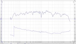
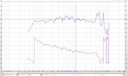
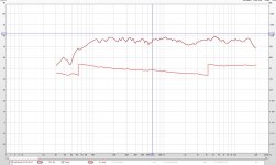
I made some new measurements which gave a lot better simulation results! Something was wrong in my SPL-measurements previously. I measured raw SPL and phase (phase corrected in REW with time reference channel) for both drivers (images 1 and 2). On axis, mic at tweeter height, 50 cm distance from baffle.
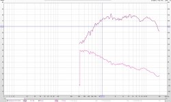
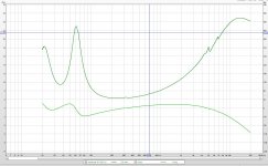
I also measured impedances including phase (images 3 and 4).
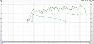
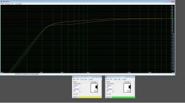
These SPL and impedance files give a pretty accurate simulated sum response in Jeff Bagby's WinPCD (comparison in image 5: upper, green curve from my speaker measurement; below it the black sum curve from WinPCD simulation).
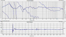
Simulated phase and measured phase don't quite match above 3kHz (image 6).
I didn't do any fiddling with acoustic offsets since I used measured phases instead of calculated minimum phases. I made a measurement of the raw drivers in parallel (above 300 Hz) though, so it's still possible to try minimum phases and acoustic offsets if necessary.
My measurement rig might be flawed at high frequencies, for I get a quite steep roll-off above 15 kHz. I measured for reference a Boston acoustics A25 that has been in use for couple of months now and shouldn't have any tweeter issues. Also a similar roll-off (image 7).
I also measured impedances including phase (images 3 and 4).
These SPL and impedance files give a pretty accurate simulated sum response in Jeff Bagby's WinPCD (comparison in image 5: upper, green curve from my speaker measurement; below it the black sum curve from WinPCD simulation).
Simulated phase and measured phase don't quite match above 3kHz (image 6).
I didn't do any fiddling with acoustic offsets since I used measured phases instead of calculated minimum phases. I made a measurement of the raw drivers in parallel (above 300 Hz) though, so it's still possible to try minimum phases and acoustic offsets if necessary.
My measurement rig might be flawed at high frequencies, for I get a quite steep roll-off above 15 kHz. I measured for reference a Boston acoustics A25 that has been in use for couple of months now and shouldn't have any tweeter issues. Also a similar roll-off (image 7).
Attachments
-
 Woofer raw SPL 1 per 24 oct smoothing - phase corrected with time reference.JPG161.9 KB · Views: 86
 -
 Tweeter raw SPL 1 per 24 oct smoothing - phase corrected with time reference.JPG150 KB · Views: 85
 -
 Woofer impedance.JPG166.6 KB · Views: 76
 -
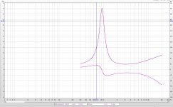 Tweeter impedance.JPG162.3 KB · Views: 73
 -
 Measured speaker SPL vs WinPCD simulated SPL.JPG186.4 KB · Views: 36
 -
 Measured speaker phase vs WinPCD simulated phase.JPG204.5 KB · Views: 41
 -
 Boston A25 1 per 24 octave smoothing.JPG155.7 KB · Views: 32
This looks like a delay difference, ie they could have the same phase. You could try adjusting the offset for no reason other than to make this comparison.Simulated phase and measured phase don't quite match above 3kHz (image 6).
Measured is generally better than a minimum phase esitmate. This kind of baffle with the driver offset vertically and horizontally is designed not to optimise the baffle behaviour, but to balance the errors at the listening position and the baffle contribution isn't necessarily going to be minimum phase.
Anyways, I'm trying to make the speakers sound good.
Where I'm at, is:
- The woofer directivity goes drastically up after 2500 Hz, so I don't want to be crossing anywhere over 2500 Hz.
- The tweeter resonance frequency is at 917 Hz so I don't want to cross anywhere below 1834 Hz.
Where I'm at, is:
- The woofer directivity goes drastically up after 2500 Hz, so I don't want to be crossing anywhere over 2500 Hz.
- The tweeter resonance frequency is at 917 Hz so I don't want to cross anywhere below 1834 Hz.
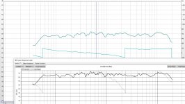
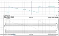
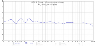
Just as an example, here is an in room measurement I did this afternoon after some adjustments, using mmm (moving mic measurement) technique.
RTA 1/48th with periodic pink noise. then smoothed to 1/6th octave.
The big humps and dips below 200Hz are mostly the room, but there is a dip in the woofers response at around 70Hz. In general look at it from 200Hz up you can see that it is tapering down. I was noticing some brightness, and have adjusted the bass (crossover freq is 270hz) up about 1db, definitely sounds a bit more balanced now I think. Will need some listening time to get used to the change.
As a comparison, the second is a normal swept sine measurement at the listening position. Mic positioned to ensure equal distance between speakers (only one pieak in impulse). You can see the MMM smooths out the peaks below 200Hz somewhat.
Tony.
Attachments
Last edited:
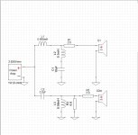
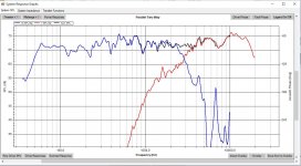
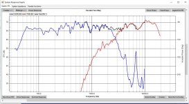
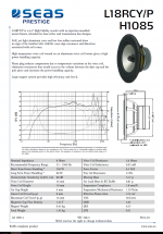
I'll take another try with a bit flatter response. What I think I really messed up with though is the RLC circuit parallel to the woofer. I altered the capacitor from 8,6 to 10 µF. I aimed at smoothing the response at 4-5 kHz, but I think the 7 kHz resonance spike is now pushing through especially off axis (Image 1 with 8,6 µF and image 2 with 10 µF - simulation in WinPCD). Although the woofer off axis response rolls off pretty steeply from 2500 Hz the resonance spikes are still there at 60 degrees off axis (image 3 - manufacturer spec sheet).
Attachments
That is a big breakup peak!! Have you tried a lower q notch centered at around 5.5Khz to try and take out both the 4K and 7K at the same time? I've played around in sims with multiple RLC's in parallel with the woofer and it seems doable, not sure how well it works in real life though.
I take it the dip around 7Khz is not inherent to the tweeter, but is the woofer breakup interfering (out of phase) with the tweeter at that frequency?
How are you doing the above measurements? Are they in room? For the actual crossover design you are best off using quasie anechoic measurements (gated, and if at all possible taken outside). You can splice in nearfield (and adjust for baffle step) for frequencies under 200 - 300Hz.
Tony.
The 7 kHz dip is unfortunately inherent to the tweeter (or caused by baffle geometrics). Also the tweeters are on the edge of adulthood at age of 18 years, so there might be some side effects from maturing. 
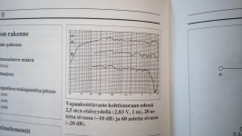
I really liked the original design by ear. Now that I look again at the SPL curve from that one (image 1 from the book by Pekka Tuomela) I notice that
- there's no ascending towards high frequencies
- the 7 kHz dip is there.
There's also a slight roll off from 200 Hz towards low frequencies by design. It's due to a bit "over sized" box and made the speakers very light to listen and also extended the bass response a bit towards 40 Hz. My current woofer handles a bigger box so the roll off isn't there anymore (image 2 - a WinISD box response simulation of the old woofer, green curve, and the new woofer, yellow curve).
I did also try with two RLC circuits. They manage the resonance spikes really well, but the problem is a really steep roll off caused by the two RLC circuits together. With two RLCs I ended up crossing at 1,5 kHz or so. I think I'll have to give it one more try though, for I'm using a lot smaller inductor now.
Attachments
The measurements are in a room. Unfortunately I can't take measuring outside, for I live in a densely populated area and there's always quite a lot of background noise outside.
How does near field splicing work? I should also try some gating. I tried some windowing in REW but the results looked pretty skewed. Luckily I don't have to try getting any reliable measurements at low (sub 100 Hz) frequencies to get the crossover done.
How does near field splicing work? I should also try some gating. I tried some windowing in REW but the results looked pretty skewed. Luckily I don't have to try getting any reliable measurements at low (sub 100 Hz) frequencies to get the crossover done.
for nearfield splicing I used the following --> FRD Blender and Minimum Phase Extractor Nearfield with a vented box is a bit tricky though. You have to measure both the woofer and the port and then combine the two (using the correct scaling) to get the overall nearfield result.
In room is OK if you can't go outside, but you need to be careful, and I would use gated measurements.
Try and set the speaker up in the middle of the room, about equal height from the floor and the ceiling.
Try and get furniture away as much as possible.
Set your mic up (and speaker) so you are not at right angles to any wall (try and aim diagonally accross the room).
Try and put some thick quilts or similar on the floor between the speaker and the mic
Don't put the mic further away than the distance from the speaker to the floor or the ceiling.
Doing this and gating the measurement before the first reflection should see you getting good measurements down to 300 - 400Hz.
I've not really tried gated measurements with REW (I've use holm impulse for gated) but It should be able to do it.
Even doing outside measurements, the best I've been able to get gated, is about 200Hz.
Tony.
- Status
- This old topic is closed. If you want to reopen this topic, contact a moderator using the "Report Post" button.
- Home
- Loudspeakers
- Multi-Way
- A daunting first (re)design