Just reviewed the simulation waveforms in post 1488 and did not see anything on the bandpass parameters in general or port particle velocity vs hole size in particular. Given what the holes can do to the polars, I think it would be worth the effort to make sure they aren't oversize. I suppose you already did that further back in the thread?
I know that with a good frustrum you have a much shorter effective port length and therefore a smaller hole will suffice. The trouble with frustrums is they allow more air under the cone which can pull the upper end down. Can you simulate frustrums in Akabak?
I know that with a good frustrum you have a much shorter effective port length and therefore a smaller hole will suffice. The trouble with frustrums is they allow more air under the cone which can pull the upper end down. Can you simulate frustrums in Akabak?
Frustrums can be approximated by the effective port length (thickness of horn wall) and change in band pass chamber volume. I made 3d printed conformal volume plugs to reduce the volume but frustrum not possible as horn wall is curved and it took significant thickness to make an adapter from curved wall to flat driver bezel mount. A lot of volume lost there relative to a horn with a flat wall where driver can be bolted to wall. But since we are doing a FAST with XO circa 600Hz, not having to eeck out a high as possible rolloff in the upper band was nice. I did look at velocities but can't remember if plotted - certainly was an important consideration. The rising bulge of the bandpass injection certainly shows up and that is generally EQ'd out or filtered with a high pass filter.
At some point you just have to take a deep breath, pick up your drill, and go for it!
Very true but I need to decide which drivers to buy first! I can buy the 8" SB's and make a bushmeister clone, but I wanted to explore the possibility of a smaller and different shaped enclosure as a big square box or sphere aren't my preferred options.
If that is the 18 Sound XT1464 WG that Bushmeister used, the Akabak sim that I did for Fluid with the smaller drivers is indeed for the XT1464 WG profile.
Yes that is the XT1464 that I have.
Looking at the pictures again the two hole placement looks better, so there is one decision!You can move in a bit more but 2 smaller holes is better than one big one I think.
Frustrums can be approximated by the effective port length (thickness of horn wall) and change in band pass chamber volume. I made 3d printed conformal volume plugs to reduce the volume but frustrum not possible as horn wall is curved and it took significant thickness to make an adapter from curved wall to flat driver bezel mount. A lot of volume lost there relative to a horn with a flat wall where driver can be bolted to wall. But since we are doing a FAST with XO circa 600Hz, not having to eeck out a high as possible rolloff in the upper band was nice. I did look at velocities but can't remember if plotted - certainly was an important consideration. The rising bulge of the bandpass injection certainly shows up and that is generally EQ'd out or filtered with a high pass filter.
Getting higher frequency bandpass output isn't really necessary with a 600Hz crossover but being able to use smaller holes would be good. Smaller holes that can be placed closer to the edges of the waveguide might well do less damage to the polars. With a smaller driver I think that I can get it 'flatter' to the horn so there will be less port length from filling in that space with epoxy.
X, could you run that sim with different size holes closer to the throat to see the effect? 120mm to 160mm from the throat should be physically possible with a 6.5" driver.
Those are Bushmeister's polars (18 Sound WG). Despite the cone being a nominal 65mm dia, it necks down through a 1.4in dia waveguide throats with a smooth adapter. As I recall, there are many CD's with 2in or 3in diaphragms that when fitted to a waveguide that smoothly helps to allow the plane wavefronts to exit the throat cleanly, you can get smooth polars. They did not start that way - if you had read the thread there were weeks and weeks of development of the transition throats that made that possible. I had 3 different 3D printed adapters plus it had to be the SB65. I could not get it to work with other drivers.
Here are my polars which used Faital Pro Tractrix WG:
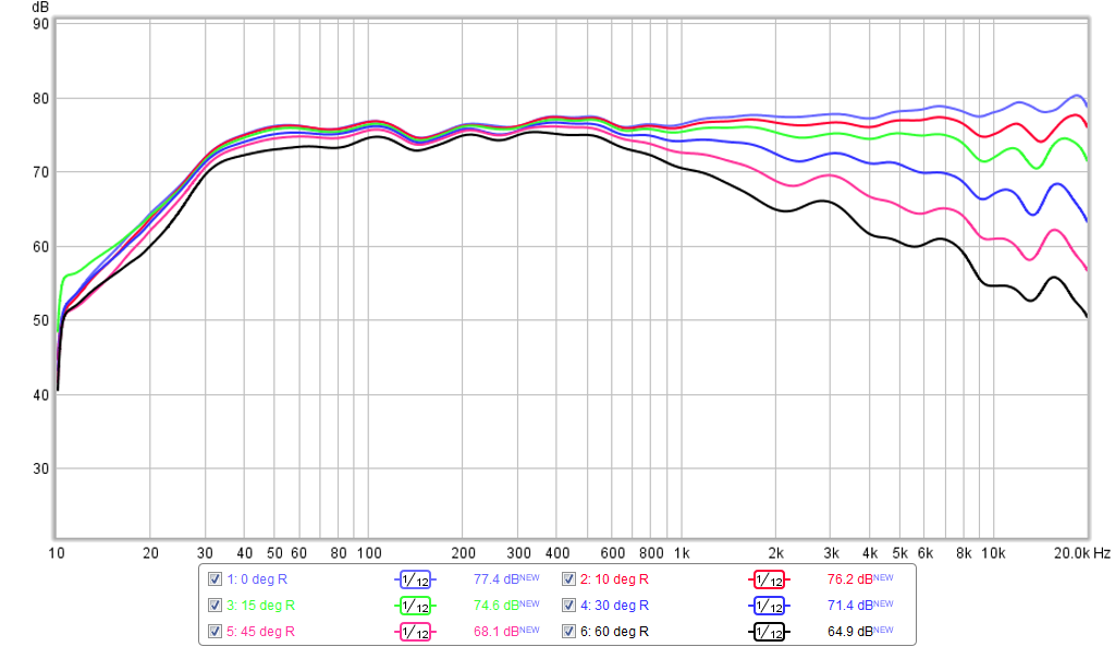
Ok, yes.....very smooth. Not constant directivity though, but narrowing directivity so from a practical standpoint, I see no advantage over a standard two way speaker whose wide, but 'constant' directivity results in an even power response.
Hi Mayhem - those are my measurements. Prob best if you actually read this thread 😉
But I thought a short video would be enlightening - this is a 1 min video of me doing three measurements to demonstrate the CD, and the lack of off axis break up........I appreciate that this is quick and dirty and not accurate - but I have done it just now after reading your comment - this is not my usual practice!
https://www.youtube.com/watch?v=KDoqqzi7C_U&feature=youtu.be
I did read the thread.........and thank you for posting your measures.......which goes again to my point of inaccuracies somewhere, whether it be the mic, sound card, software or a combination of things. Loading the driver in a guide can't move the breakup higher in frequency, nor can it smooth a 10db off axis null to flat. Furthermore, your polars aren't normalized so they look a lot smoother than they actually are. That would show the normal, expected waste banding that the manufactures flat baffle measurements suggest.
Ok, yes.....very smooth. Not constant directivity though, but narrowing directivity so from a practical standpoint, I see no advantage over a standard two way speaker whose wide, but 'constant' directivity results in an even power response.
The graph your are referring to is based on tractrix waveguide which by design has narrowing directivity with frequency as shown in the manufacturers plots.
The XT1464 that was also used has a flatter DI and bushmeister's results match quite well with the manufacturers graphs, if it is within 6dB and 30 degree each way it is within the design of the waveguide.
Controlled directivity is usually a better word than constant.
I don't know of a standard 2 way speaker with constant directivity and they usually have a slightly falling power response.
Even so they work well if placed far enough out into the room to avoid too much early room interference.
The point of designs like these is that they have a tighter beam width and therefore they can work better in a untreated room as they don't spray so much sound on the floor ceiling and sidewalls.
If you don't think that is good idea then these type of designs are not for you.
I did read the thread.........and thank you for posting your measures.......which goes again to my point of inaccuracies somewhere, whether it be the mic, sound card, software or a combination of things. Loading the driver in a guide can't move the breakup higher in frequency, nor can it smooth a 10db off axis null to flat. Furthermore, your polars aren't normalized so they look a lot smoother than they actually are. That would show the normal, expected waste banding that the manufactures flat baffle measurements suggest.
Any driver in a waveguide will respond directly than on a flat baffle. A compression driver has a completely different response when on a plane wave tube to a waveguide. This is why the combination of driver and waveguide is important some work well together some do not. I don't understand why you would think it should look the same.
Both designs in this thread have quite a lot of DSP EQ applied in the later graphs so some of the faults may have been smoothed over.
It shouldn't look the same, a change in the response amplitude is expected, but not a shift in frequency for an impedance induced peak or resonance.
Controlled isn't the better word as directivity can be controlled by nearly any mechanical altering of the wavefront. Controlling directivity how?........narrow, constant, expanding?.......you pick the acronym that best suits a desired loudspeaker trait?
Narrowing is a pointless effort.......circular emmitors do this just fine on their own. If that's your thing, build eight foot long PWTs and focus them on your listening position.
Yes, speakers with a level of directivity do allow for less reflective surrounding interference to the fundamental.........that's a given. I question the use of a 2.5" direct radiator whose 'directivity' as you put it is so poor against comparison to 1" and smaller devices.
Remember to ask the questions Could and Should which have completely different meanings.
And for those using wide horizontal devices with narrow vertical in the home environment I ask why?.......are your walls less reflective than your floor or ceiling?......or are we just following along the developed lines of these devices in very large or open spaces.....to maintain wide angle coverage for large audiences with less devices required? Again, an important question.
@FLUIDThe graph your are referring to is based on tractrix waveguide which by design has narrowing directivity with frequency as shown in the manufacturers plots.
The XT1464 that was also used has a flatter DI and bushmeister's results match quite well with the manufacturers graphs, if it is within 6dB and 30 degree each way it is within the design of the waveguide.
Controlled directivity is usually a better word than constant.
I don't know of a standard 2 way speaker with constant directivity and they usually have a slightly falling power response.
Even so they work well if placed far enough out into the room to avoid too much early room interference.
The point of designs like these is that they have a tighter beam width and therefore they can work better in a untreated room as they don't spray so much sound on the floor ceiling and sidewalls.
If you don't think that is good idea then these type of designs are not for you.
Any driver in a waveguide will respond directly than on a flat baffle. A compression driver has a completely different response when on a plane wave tube to a waveguide. This is why the combination of driver and waveguide is important some work well together some do not. I don't understand why you would think it should look the same.
Both designs in this thread have quite a lot of DSP EQ applied in the later graphs so some of the faults may have been smoothed over.
A compression driver on a plane wave tube is near enough the same response on a large constant directivity waveguide example jbl 2360a
Every wave guide will differ to a plane wave tube response size and shape changes everything
It's just exploiting the wave guide for your own use and matching of a particular drivers response
Last edited:
Hi Mayhem,
Thank you for your interest in this design.
It is good to ask questions, but your logic and arguments are so flawed and inconsistant, I don't know where to start.
You begin with this:
First regarding your directivity point.....
Lets look at a normal CD:
Here are a few stimulating questions to ponder regardin this topic:
Why does a 3" or even 4" diaphragm in a compression driver not have the polar measurements of a 3" or 4" diaphragm?
Why does it's directivity more closely match that of it's exit diameter rather than its diaphragm diameter?
Why does a 2" exit CD with the same diaphragm diameter have a worse polar response to a 1" exit CD?
What is the difference between the anatomy of my SB65 mounted to a horn with a 1.4" throat and the above diagram of a compression driver?
Why do you think therefore that the dispersion of the 2.5" diaphragm will not be affected by the 1.4" exit diameter of the horn?
Moving outside of the anatomy of the CD itself,
Why do a whole host of horns/waveguides have diffraction slots/pinch throats?
Are these horns designed specifically to affect polar response or just for fun?
Does the fact that these horns/waveguides have various throat designs indicate that the throat design itself can influence the polar response of the driver in different ways?
These are good questions I think......
Moving on.
You are right it is not in my graphs.....and you insinuate that the horn/waveguide cannot affect this 'nasty off axis break up' so my measurements must be wrong........
Then you see XrK's graph and say:
Wow! Hold up, you just accepted his polar response??? You even comment how smooth it is, right?
Yep I didn't imagine that.
But Mayhem, - this is the same driver - the SB65?
You have stated that the "Nasty off axis break up" ....."can't be corrected with mechanics or XO components" Then you completely ignore that XrK's measurements also show an absence of it, and completely echo my own measurements....
You come back to my measurements - ignoring again the fact that XrK's and mine are the same driver on different horns....
Maybe both our microphones are broken?, one in the UK and one in the USA?
Maybe we are both using the very same sound card which miraculously changes the off axis measurements in the same way.......? How weird that both our measurements show the same smooth off axis response (although obviously they seem to show that the different horn designs are affecting the polar response in different ways - one looks more 'tractrix' the other more 'constant directivity'......that's weird too right? - or are the horns doing the job they were designed for.....?)
Weird how two experienced DIY'ers have both loaded the SB65 into different horns, at different times, using completely different measurement gear, on opposite sides of the globe and demonstrated the same off axis behavior which is....
Yep. Smooth. Hmmmmmm
Back to this - why then do most compression drivers use 3-4" diaphragms? Oh wait - we have already looked at this - take off the exit throat of a CD and phase plug and it will behave like a 3-4" direct radiator - but the throat changes everything......
Interestingly the off axis reponse of the SB65 is almost as good as some 1" tweeters:

Also I suspect better than a 3" compression driver with it's throat and phase plug removed.....
Actually this last point is a good one - and the reason I made my design switchable.
Mayhem - I do appreciate your interest and stimulating arguments. If I am a little defensive here it is because you are rubbishing my measurements and seem to be making contradictory and illogical arguments.
Please feel free to reply robustly too! 🙂
Thank you for your interest in this design.
It is good to ask questions, but your logic and arguments are so flawed and inconsistant, I don't know where to start.
You begin with this:
Your polars aren't accurate,.....given the piston diameter of the SB, directivity from the center of the cone above the wavelegth HAS to fall......pure phyics unfortunately.
First regarding your directivity point.....
Lets look at a normal CD:
An externally hosted image should be here but it was not working when we last tested it.
Here are a few stimulating questions to ponder regardin this topic:
Why does a 3" or even 4" diaphragm in a compression driver not have the polar measurements of a 3" or 4" diaphragm?
Why does it's directivity more closely match that of it's exit diameter rather than its diaphragm diameter?
Why does a 2" exit CD with the same diaphragm diameter have a worse polar response to a 1" exit CD?
What is the difference between the anatomy of my SB65 mounted to a horn with a 1.4" throat and the above diagram of a compression driver?
Why do you think therefore that the dispersion of the 2.5" diaphragm will not be affected by the 1.4" exit diameter of the horn?
Moving outside of the anatomy of the CD itself,
Why do a whole host of horns/waveguides have diffraction slots/pinch throats?
Are these horns designed specifically to affect polar response or just for fun?
Does the fact that these horns/waveguides have various throat designs indicate that the throat design itself can influence the polar response of the driver in different ways?
These are good questions I think......
Moving on.
Also the IB graphs of the SB have an usual nasty off axis breakup that your graph doesn't show that can't be corrected with mechanics or XO components.........but mysteriously it's not in your graph.
You are right it is not in my graphs.....and you insinuate that the horn/waveguide cannot affect this 'nasty off axis break up' so my measurements must be wrong........
Then you see XrK's graph and say:
Ok, yes.....very smooth. Not constant directivity though, but narrowing directivity so from a practical standpoint, I see no advantage over a standard two way speaker whose wide, but 'constant' directivity results in an even power response.
Wow! Hold up, you just accepted his polar response??? You even comment how smooth it is, right?
Ok, yes.....very smooth.
Yep I didn't imagine that.
But Mayhem, - this is the same driver - the SB65?
You have stated that the "Nasty off axis break up" ....."can't be corrected with mechanics or XO components" Then you completely ignore that XrK's measurements also show an absence of it, and completely echo my own measurements....
You come back to my measurements - ignoring again the fact that XrK's and mine are the same driver on different horns....
I did read the thread.........and thank you for posting your measures.......which goes again to my point of inaccuracies somewhere, whether it be the mic, sound card, software or a combination of things. Loading the driver in a guide can't move the breakup higher in frequency, nor can it smooth a 10db off axis null to flat.
Maybe both our microphones are broken?, one in the UK and one in the USA?
Maybe we are both using the very same sound card which miraculously changes the off axis measurements in the same way.......? How weird that both our measurements show the same smooth off axis response (although obviously they seem to show that the different horn designs are affecting the polar response in different ways - one looks more 'tractrix' the other more 'constant directivity'......that's weird too right? - or are the horns doing the job they were designed for.....?)
Weird how two experienced DIY'ers have both loaded the SB65 into different horns, at different times, using completely different measurement gear, on opposite sides of the globe and demonstrated the same off axis behavior which is....
Ok, yes.....very smooth.
Yep. Smooth. Hmmmmmm
I question the use of a 2.5" direct radiator whose 'directivity' as you put it is so poor against comparison to 1" and smaller devices.
Back to this - why then do most compression drivers use 3-4" diaphragms? Oh wait - we have already looked at this - take off the exit throat of a CD and phase plug and it will behave like a 3-4" direct radiator - but the throat changes everything......
Interestingly the off axis reponse of the SB65 is almost as good as some 1" tweeters:
Also I suspect better than a 3" compression driver with it's throat and phase plug removed.....
Remember to ask the questions Could and Should which have completely different meanings.
And for those using wide horizontal devices with narrow vertical in the home environment I ask why?.......are your walls less reflective than your floor or ceiling?......or are we just following along the developed lines of these devices in very large or open spaces.....to maintain wide angle coverage for large audiences with less devices required? Again, an important question.
Actually this last point is a good one - and the reason I made my design switchable.
Mayhem - I do appreciate your interest and stimulating arguments. If I am a little defensive here it is because you are rubbishing my measurements and seem to be making contradictory and illogical arguments.
Please feel free to reply robustly too! 🙂
Last edited:
I was trying to use the example to show that that the response of any driver will be different when in a waveguide or horn.
This graph might show it better the bottom trace shows that the driver and waveguide work well together. The frequency and impedance plots are quite different between the horn and tube.

Mayhem you seem to have made your mind up that this design and the measurements are flawed, I disagree so I will leave it there before this hole gets any deeper....
too late bushmeister posted at the same time with a more thorough version of what I said before 🙂
This graph might show it better the bottom trace shows that the driver and waveguide work well together. The frequency and impedance plots are quite different between the horn and tube.
Mayhem you seem to have made your mind up that this design and the measurements are flawed, I disagree so I will leave it there before this hole gets any deeper....
too late bushmeister posted at the same time with a more thorough version of what I said before 🙂
Last edited:
Ok, yes.....very smooth. Not constant directivity though, but narrowing directivity so from a practical standpoint, I see no advantage over a standard two way speaker whose wide, but 'constant' directivity results in an even power response.
Unless you look at the 2 way in the vertical plane...
Thanks Xrk!
The plan is: one flare big conical horn, as Legis built. 90cm wide, 60cm high, 70cm deep. One 12PE32 for 130-600hz, and the SB65 for mids&highs. Will post in few days the progress, I am waiting for the MDF and SB65 to be delivered.
The conical is a better way then a tractrix because the load to the speaker is better when injecting, the sound is more spread with a conical horn, but I have to say the tractrix do quite good, I like the sound.
I am curious for the results.
X I have park the amp project some days, because I have other work and it is sometimes better to do something else, like get the outside place oke, because of winter who is coming.
regards
Last edited:
a change in the response amplitude is expected, but not a shift in frequency for an impedance induced peak or resonance.
That's exactly what a waveguide does: it changes the acoustic impedance relative to a flat baffle. Hence, what may have been a dip or fall off with a flat baffle will be completely different with a waveguide.
on the topic of holes is it area or cross section that affects response as a low pass?
sorry just need a sanity check as i'm stuck on an experiment and before i cut holes i just need to confirm i'm on the right track.
sorry just need a sanity check as i'm stuck on an experiment and before i cut holes i just need to confirm i'm on the right track.
It's a combination of cross sectional area and the volume of the driver band pass chamber behind it. A small hole has better band pass filtering but will have an overshoot peak. A large hole has less filtering but affects polars of HF more. A smaller volume behind hole gets higejr frequency extension. Smaller volume and smaller hole have better cone control for higher power output before xmax limits. Smalller hole has higher velocity so cannot be too small or else turbulence gives higher distortion. Lots of things inter-playing.
Need to run simulations to see how it can be optimized.
Need to run simulations to see how it can be optimized.
The conical is a better way then a tractrix because the load to the speaker is better when injecting, the sound is more spread with a conical horn, but I have to say the tractrix do quite good, I like the sound.
I am curious for the results.
X I have park the amp project some days, because I have other work and it is sometimes better to do something else, like get the outside place oke, because of winter who is coming.
regards
I am curious how Arcgotic's horn will turn out too. Good for you to take break. You have been working like a madman on that allfet circlotron.
I got the 3FE25 for mids/highs. The SB65 was not on stock and I don't want to wait. Plus, the 3FE25 has more SPL, maybe i can do a passive crossover crossed to 12PE32.
What throat entry do you recommend? I am thinking of going from 3" to 2" diameter before entering the conical horn.
If the 3FE25 will go to 10kHz, I am OK with it. I can add a Fostex cheap supertweerer later if needed..
The MDF has arrived. Pictures soon.
What throat entry do you recommend? I am thinking of going from 3" to 2" diameter before entering the conical horn.
If the 3FE25 will go to 10kHz, I am OK with it. I can add a Fostex cheap supertweerer later if needed..
The MDF has arrived. Pictures soon.
I've generally found that it's nearly impossible to get a direct radiator to sound good with a reverse taper. Basically you get reflections off the throat, and due to the pathlength differences you wind up with comb filtering. And it sounds raspy.
(At 10,000hz, a pathlength difference of just one centimeter will cause issues, due to the very short wavelengths.)
Basically you'll get better results if the horn or waveguide has a positive taper from the diaphragm all the way to the mouth.
(At 10,000hz, a pathlength difference of just one centimeter will cause issues, due to the very short wavelengths.)
Basically you'll get better results if the horn or waveguide has a positive taper from the diaphragm all the way to the mouth.
That's a pinch point as Bushmeister and I had to do it to get the the SB65WB to fit the 1.4in throat and it was critical to make it smooth to avoid cancellation reflections. 3in diphragm CD's do this all the time (with help of phase plug).
- Home
- Loudspeakers
- Multi-Way
- A Bookshelf Multi-Way Point-Source Horn