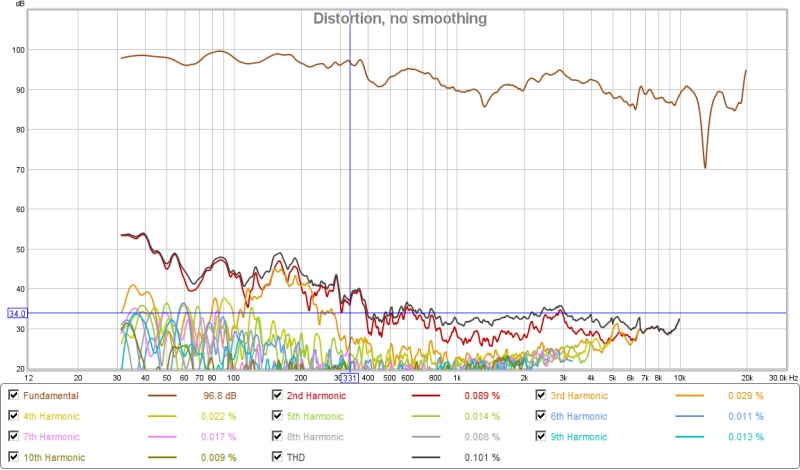
50dB below is pretty good low HD if you are able to achieve that with a CD. Can you share some plots similar to the xBush so I can get a sense of the HD?
Look at post 114 in my synergy corner horn thread
http://www.diyaudio.com/forums/multi-way/291160-my-synergy-corner-horn-bass-bins-12.html
there may be a higher resolution plot later on but that tells the story. I'm about to update the thread with results up in my room instead of in the garage
This will take you to the graph as the images in post
#114 didn't work for me
http://www.diyaudio.com/forums/attachments/multi-way/566626d1472138046-my-synergy-corner-horn-bass-bins-tda-nld-dsp-dleay-tweaked-xo.jpg
Or go to post #126 for all the pictures
#114 didn't work for me
http://www.diyaudio.com/forums/attachments/multi-way/566626d1472138046-my-synergy-corner-horn-bass-bins-tda-nld-dsp-dleay-tweaked-xo.jpg
Or go to post #126 for all the pictures
How is the SB65WB25AC beaming above 5kHz? Where is 5kHz "beaming" seen in the polar plots below?

What profile is that horn? Tractrix, if I recall correctly.
Beaming may be too strong a term for the curve you show but you can see the tendency there. The downward slope of the off axis curves increasing above 3 Khz starting for the third curve down off axis. If you are very far off axis you won't hear much treble but I expect in the first 20 degrees or so it will be fine. Those are good polars but I think the polars in Bill's Small Syns based on a constant directivity SEOS15 are better.
Its true that a direct radiator beams at a frequency related to its diameter but not necessarily so for a horn. To the extent that the throat transition and phase plug, if any, succeeds in converting the plane wave from the direct radiator's piston to the wave shape optimal for the horn profile, then the dispersion should be as dictated by the horn profile. I think tractrix does have moderate HF beaming but apparently not nearly as much as LeCleach.
Here the throat transition being just round to round was less of a challenge than a typical rectangular wooden conical horn but it still required and received careful attention, as I recall.
This will take you to the graph as the images in post
#114 didn't work for me
http://www.diyaudio.com/forums/attachments/multi-way/566626d1472138046-my-synergy-corner-horn-bass-bins-tda-nld-dsp-dleay-tweaked-xo.jpg
Or go to post #126 for all the pictures
thanks for covering for me. Yes, my early posts used google photo which was problematic
Here is a link to post 126
http://www.diyaudio.com/forums/multi-way/291160-my-synergy-corner-horn-bass-bins-13.html
thanks for covering for me. Yes, my early posts used google photo which was problematic
Here is a link to post 126
http://www.diyaudio.com/forums/multi-way/291160-my-synergy-corner-horn-bass-bins-13.html
Thanks for that. What reference SPL levels were these HD's taken at?
What profile is that horn? Tractrix, if I recall correctly.
Beaming may be too strong a term for the curve you show but you can see the tendency there. The downward slope of the off axis curves increasing above 3 Khz starting for the third curve down off axis. If you are very far off axis you won't hear much treble but I expect in the first 20 degrees or so it will be fine. Those are good polars but I think the polars in Bill's Small Syns based on a constant directivity SEOS15 are better.
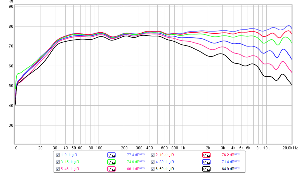
Hi, those are my measurements. That is a CD horn. SOTA XT1464. It has excellent 60 degree horizontal Polars. The first two lines on that graph are actually overlapped so difficult to see apart. They are 10 degree increments indicating that up until ~60 degrees there is excellent CD from approx 700hz upwards.
You are right that the SEOS are CD to about 90, but I chose 60 degrees as I plan to have them fairly far back from the listening position and didn't want to have to use too much side wall absorption. Given the 60 degree coverage, and placement, they should illuminate a three seater sofa with no audible beaming.
Last edited:
Thanks for that. What reference SPL levels were these HD's taken at?
Sorry, I don't have a number. All I can say is I found the measurement chirp to be loud.
How is the SB65WB25AC beaming above 5kHz? Where is 5kHz "beaming" seen in the polar plots below?
Your polars aren't accurate,.....given the piston diameter of the SB, directivity from the center of the cone above the wavelegth HAS to fall......pure phyics unfortunately.
Also the IB graphs of the SB have an usual nasty off axis breakup that your graph doesn't show that can't be corrected with mechanics or XO components.........but mysteriously it's not in your graph.
What's the offset degree of each color trace?.....5,10,?????
You do realise this is the polar plot of Bushmeister's Synergy, right? With the SB driver feeding the horn, with care taken in the driver to horn transition. Please let us know why this measured result isn't valid.Your polars aren't accurate,.....given the piston diameter of the SB, directivity from the center of the cone above the wavelegth HAS to fall......pure phyics unfortunately.
Also the IB graphs of the SB have an usual nasty off axis breakup that your graph doesn't show that can't be corrected with mechanics or XO components.........but mysteriously it's not in your graph.
What's the offset degree of each color trace?.....5,10,?????
Last edited:
Your polars aren't accurate,.....given the piston diameter of the SB, directivity from the center of the cone above the wavelegth HAS to fall......pure phyics unfortunately.
Also the IB graphs of the SB have an usual nasty off axis breakup that your graph doesn't show that can't be corrected with mechanics or XO components.........but mysteriously it's not in your graph.
What's the offset degree of each color trace?.....5,10,?????
Those are Bushmeister's polars (18 Sound WG). Despite the cone being a nominal 65mm dia, it necks down through a 1.4in dia waveguide throats with a smooth adapter. As I recall, there are many CD's with 2in or 3in diaphragms that when fitted to a waveguide that smoothly helps to allow the plane wavefronts to exit the throat cleanly, you can get smooth polars. They did not start that way - if you had read the thread there were weeks and weeks of development of the transition throats that made that possible. I had 3 different 3D printed adapters plus it had to be the SB65. I could not get it to work with other drivers.
Here are my polars which used Faital Pro Tractrix WG:
The way Bushmeister has crafted the transition from the SB65 cone to the waveguide throat creates a smooth "pinch" in that that the area goes from large at the cone to smaller at the waveguide entrance and then larger again all smoothly contoured.
Many waveguides have a pinched throat to improve high frequency directivity. Bushmeister's modifications create the same effect and could explain why the result is better than expected.
Many waveguides have a pinched throat to improve high frequency directivity. Bushmeister's modifications create the same effect and could explain why the result is better than expected.
Your polars aren't accurate,.....given the piston diameter of the SB, directivity from the center of the cone above the wavelegth HAS to fall......pure phyics unfortunately.
Also the IB graphs of the SB have an usual nasty off axis breakup that your graph doesn't show that can't be corrected with mechanics or XO components.........but mysteriously it's not in your graph.
What's the offset degree of each color trace?.....5,10,?????
Hi Mayhem - those are my measurements. Prob best if you actually read this thread
")
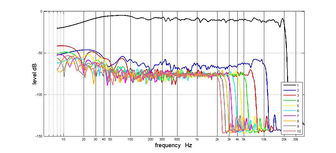
But I thought a short video would be enlightening - this is a 1 min video of me doing three measurements to demonstrate the CD, and the lack of off axis break up........I appreciate that this is quick and dirty and not accurate - but I have done it just now after reading your comment - this is not my usual practice!
https://www.youtube.com/watch?v=KDoqqzi7C_U&feature=youtu.be
Nice live demo of polar measurements there - what happened to the sound? Those speakers look great btw.
Cheers X!
I forgot to turn the sound on.
They still need another coat of matt varnish and a little cosmetic TLC. But I am very pleased with the result over all - much better than the previous huge boxes.
They obviously don't fit with the existing decor in my study, so will be moved as soon as my listening room is done.
The ports were located 50mm dia (axial distance) from the exit plane of the mouth of the waveguide.
Yes, qnty 2 x 40mm dia ports per driver.
I have been trying to work out port placement and size if I go go with the 6.5" drivers.
Here are some images to demonstrate some options.
56mm port (almost same csa as 2 x 40mm) 120mm axially from the throat

6.5" driver size with 56mm port in the centre mounted where centre of port is at 120mm axially

2 x 40mm ports at 120mm


6.5" size mounting position with 2 x 40mm ports

If the driver is mounted almost against the back flange of the waveguide then the ports could be at 80mm axially if centred on the driver. Seems to be quite a lot of port very close to the fullrange.
The ports can go further than 120mm if they are moved off centre or the driver down the horn ,but if I move them much more I might as well use the 8" inch driver, any thoughts?
Fluid - placing port closer to throats has advantage of allowing higher upper cutoff for the bass xo or allows shallower xo slopes to be used. Biggest downside is that it may impact the high frequency polar directivity and smoothness. Only way to know is either 3D FEA model or experiment. If I were you, I would keep it closer to the mouth as designed and tested by Bushmeister. You can move in a bit more but 2 smaller holes is better than one big one I think.
At some point you just have to take a deep breath, pick up your drill, and go for it!
I don't expect you have a simulation model for that waveguide but you can simulate the bandpass chambers, hole size. and port length and gain some confidence you aren't making the holes TOO large
I don't expect you have a simulation model for that waveguide but you can simulate the bandpass chambers, hole size. and port length and gain some confidence you aren't making the holes TOO large
I don't expect you have a simulation model for that waveguide but you can simulate the bandpass chambers, hole size. and port length and gain some confidence you aren't making the holes TOO large
If that is the 18 Sound XT1464 WG that Bushmeister used, the Akabak sim that I did for Fluid with the smaller drivers is indeed for the XT1464 WG profile.
Last edited:
- Home
- Loudspeakers
- Multi-Way
- A Bookshelf Multi-Way Point-Source Horn