LineSource-
Interesting. I can see how that would give a more pistonic effect (desireable), but I have concerns that the ribbon would "crinkle" at the low frequencies I intend to run. I can see experimenting down the road though. I still may do the "accordian" thing though..still thinking on that one.
Jozua-
Thanx")
I wish I had more . Seriously though, other than the milling I'm doing now (which I'm only doing to size what I had laying around, and because I can), this entire project is being done with a drill press, a band saw (which I purchased because of this project), and a MIG welder (that I borrowed from my brother.
Ditto that.
There have been many glowing reviews of the RAAL ribbons applauding their dynamics when compared to traditional ribbon tweeters. RAAL uses a zig-zag pattern embossed (stamp or rolling press?) into the aluminum foil for strength instead of the traditional corrugated horizontal pleats. The RAAL ribbon also uses a heat shrink plastic film attached to the end of the ribbon foil as a tunable suspension which also has good reflected wave energy absorption. I think RAAL trademarks "FlatFoil" for their ribbon design.
Interesting. I can see how that would give a more pistonic effect (desireable), but I have concerns that the ribbon would "crinkle" at the low frequencies I intend to run. I can see experimenting down the road though. I still may do the "accordian" thing though..still thinking on that one.
Jozua-
It looks excellent
Thanx
Wish I had those tools at home......
I wish I had more
. Seriously though, other than the milling I'm doing now (which I'm only doing to size what I had laying around, and because I can), this entire project is being done with a drill press, a band saw (which I purchased because of this project), and a MIG welder (that I borrowed from my brother.I can wait to hear how they going to sound.
Ditto that.
...other than the milling I'm doing now (which I'm only doing to size what I had laying around, and because I can), this entire project is being done with a drill press, a band saw (which I purchased because of this project), and a MIG welder (that I borrowed from my brother.
What a stupid thing for me to say
 . I did in fact do considerable milling on the cross blocks earlier on. I should have said that it is possible to do something similar without milling capabilities..lots of filing and sanding.
Onward with the progress..
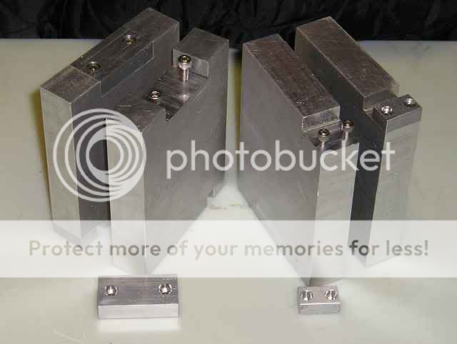
I didn't seem to have my camera with me when I did a lot of the work, so the post is a little picture light this time. After I finished sizing the aluminum blocks, I cut out the space to center the ribbon in the gap (this picture came out so well I may have it printed..the lighting is awesome)...

I then milled out a corner on the bottom, drilled and tapped the blocks, and made caps to fit in the cutouts. Here are the four finished terminal blocks. The two on the right show my solution to connecting the cable/wire. There is .5" between the screws, and this connection will be able to accommodate whatever I decide on for my speaker cables...
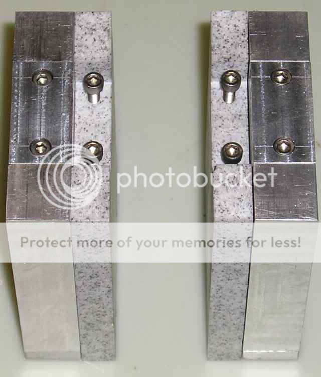
These blocks mount to the insulator blocks made of Corion that in turn mount to the ribbon frame..

If you look closely you can see the Corion block is cut .1" deeper than the aluminum. I will be laying in a piece of Sorbothane rubber that is .15" thick when relaxed. There will be a matching piece attached to the cap. I then adjust the screws on the caps (which haven't been made yet) till the foil pinched in between is in line with the aluminum block. The rubber will stop .05" from the edge mating the aluminum block giving a small void to accommodate a "roll" in the foil for a strain relief between the Corion and aluminum blocks. Here is a picture of one set to give a better idea of how it all works together...
Thats it for now. I'm getting closer though
Casey
This weekends progress...
My first task was to mill the caps for the insulator blocks. Though this was relatively easy, the small size made mounting the pieces a pain. What was supposed to be a minor chore took much longer than expected (a continuing theme for my projects ). After they were made I focused my attention on the mounting of my end assemblies. After penciling it out I realized that I needed a drilling jig. The insulator blocks required 10 holes, 5 threaded and 5 through. The termination blocks and frame ends needed 5 each. The quantity of holes that needed to line up, plus the fact that the frames needed to be drilled with a hand drill (to tall to fit in the press), made it clear that if I wanted things to come together a jig was the way to go. Much cutting, milling, drilling, and tapping ensued...

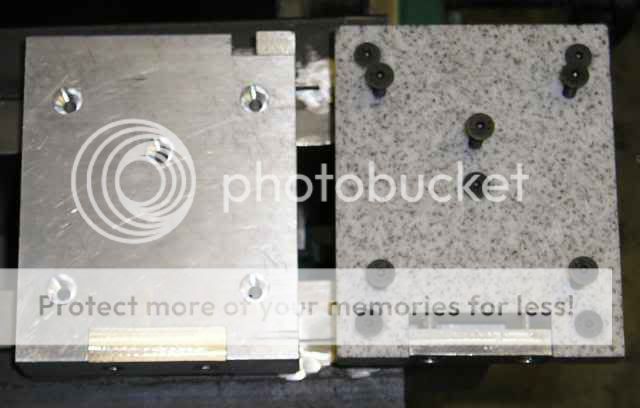
It worked a treat. The time spent making it was more than made up by the speed I was able to drill my pieces. Here are the insulator and termination blocks drilled/tapped, and ready to mount. I placed the screws in the insulator block to help visualize the mounting scheme....
And finally, here is one of the assemblies mounted to a frame end...
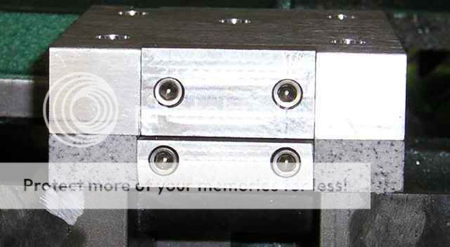
Unfortunately this is the only one mounted. I knew my tap was getting dull after the bazzilion holes it was put into service to thread, and that it needed replacing. Did I ? No. Instead I forged ahead. The result of this brilliant decision is that what is left of the expired tap is forever ensconced in one of the holes in the frame . Oh well. At least the overkill design still has 4 screws holding the insulator block on nice and tight.
Casey
My first task was to mill the caps for the insulator blocks. Though this was relatively easy, the small size made mounting the pieces a pain. What was supposed to be a minor chore took much longer than expected (a continuing theme for my projects
). After they were made I focused my attention on the mounting of my end assemblies. After penciling it out I realized that I needed a drilling jig. The insulator blocks required 10 holes, 5 threaded and 5 through. The termination blocks and frame ends needed 5 each. The quantity of holes that needed to line up, plus the fact that the frames needed to be drilled with a hand drill (to tall to fit in the press), made it clear that if I wanted things to come together a jig was the way to go. Much cutting, milling, drilling, and tapping ensued...
It worked a treat. The time spent making it was more than made up by the speed I was able to drill my pieces. Here are the insulator and termination blocks drilled/tapped, and ready to mount. I placed the screws in the insulator block to help visualize the mounting scheme....
And finally, here is one of the assemblies mounted to a frame end...
Unfortunately this is the only one mounted. I knew my tap was getting dull after the bazzilion holes it was put into service to thread, and that it needed replacing. Did I ? No. Instead I forged ahead. The result of this brilliant decision is that what is left of the expired tap is forever ensconced in one of the holes in the frame
. Oh well. At least the overkill design still has 4 screws holding the insulator block on nice and tight.Casey
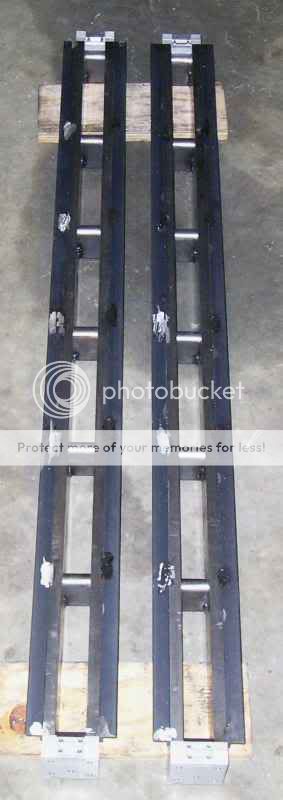
What a pain in the back side mounting the end blocks turned out to be. Having been spoiled a long time ago with a drill press, I had forgotten just how labor intensive using a a hand drill can be...especially going in horizontally without the benefit of "leaning into it". With 5 holes .6" deep on both ends of each frame, I was more than a little glad when the last hole was drilled. After snapping a tap last weekend I was also a little apprehensive of repeating that event. I was able to tap the remaining holes without incident though. So this phase of the project is behind me, and I have all end blocks mounted...
I have been having an argument with myself as the ribbons near completion. Basically I have been reconsidering my plan of having a common enclosure for both the ribbon and the transmission line. I have been having three primary reservations about this. 1) The combined weight of around 300 lbs would make moving them around a Herculean task, 2) I feel it would be wise to design the baffle empirically rather than trust my "best guess", and 3) I'm not thrilled with the aesthetic of the original plan..too "plain Jane". So, I spent the day coming up with plan "B". I will be fabricating what amounts to a pair of Christmas tree stands on steroids to support the the ribbons "free standing". This will allow me to play around with baffle design to my hearts content until I find the optimum size/shape. I'll run them with a sharp ( 4 to 6 pole) high pass filter set to 50hz or so to protect them from any infra-sonics that could damage them and play with them until I have a natural F3 of as close to 200hz as possible. From there I'll integrate the TL.
I can almost hear them now
Casey
Your labor of love
I have followed this post from the beginning i am inspired by your work ethic and quality values. I will be waiting for the final test of how well it sounds.
One question though. Have you looked into a more robust material than aluminum for the ribbon. Is there not a source for very thin titanium or stainless steel. It seems that tensioning such a fine ribbon of aluminum and repeated use would lead to premature failure.
If all goes well you have inspired me to challenge this project. Best regards and good luck Tad
Hi Tad..thanx for your interest in my little project.
The short answer is yes. If I could find Ti in the size I need (8 micron or less thick and 6 ft long) I would jump at the chance to use it. As far as stainless..not so much. True it is stronger, but the mass is way higher..it would have to be insanely thin.
As it is, Al continues to be king of the hill. The trick is to tune the resonance below the pass band so as to not stress it.
Casey
One question though. Have you looked into a more robust material than aluminum for the ribbon.
The short answer is yes. If I could find Ti in the size I need (8 micron or less thick and 6 ft long) I would jump at the chance to use it. As far as stainless..not so much. True it is stronger, but the mass is way higher..it would have to be insanely thin.
As it is, Al continues to be king of the hill. The trick is to tune the resonance below the pass band so as to not stress it.
Casey
One other thing. The plastic foil used for packageing with the aluminium coating comes in long rolls and bonded to a very strong plastic. Would that be a suitable material to use. I have also had good luck cutting very thin sheets of gold foil with a roller knife similar to a pizza cutter..
I am still looking into a source like yours for the magnets. The surplus stock is available however the shipping for heavy lots is absurd. Keep plugging away. Awaiting final results and thanks Tad
I am still looking into a source like yours for the magnets. The surplus stock is available however the shipping for heavy lots is absurd. Keep plugging away. Awaiting final results and thanks Tad
Tad,
Depends on what suitable is . It's not for me. The mass of the ribbon is directly related to it's efficiency..any extra mass (mylar backing) is to be avoided if possible. The reason it is used in commercial efforts is 2 fold. 1) it's easier to manufacture on a large scale, and 2) it makes for a product than can be abused and survive. Thin foil takes great care in construction, and you will only over power it once before your doing it again. The reward for forgoing the durability is much greater efficiency and speed.
Yep. Thats the hard part. This project would be very different if I hadn't stumbled onto the deal I did. A friend asked me how much it would cost to replace my magnets, and after a little research I found that it would run close to a thousand bucks through normal channels...ouch.
Casey
One other thing. The plastic foil used for packageing with the aluminium coating comes in long rolls and bonded to a very strong plastic. Would that be a suitable material to use
Depends on what suitable is
. It's not for me. The mass of the ribbon is directly related to it's efficiency..any extra mass (mylar backing) is to be avoided if possible. The reason it is used in commercial efforts is 2 fold. 1) it's easier to manufacture on a large scale, and 2) it makes for a product than can be abused and survive. Thin foil takes great care in construction, and you will only over power it once before your doing it again. The reward for forgoing the durability is much greater efficiency and speed.I am still looking into a source like yours for the magnets. The surplus stock is available however the shipping for heavy lots is absurd.
Yep. Thats the hard part. This project would be very different if I hadn't stumbled onto the deal I did. A friend asked me how much it would cost to replace my magnets, and after a little research I found that it would run close to a thousand bucks through normal channels...ouch.
Casey
Would it be possible to use and electromagnet type field. A configuration that would allow you to wind wire onto the pole pieces and apply constant voltage from an isolation transformer. You would have better control of the field and you could adjust to optimize for air gap.
When I finish these 3 Leach amps I know what the next project will be. Like we do not have enough to do. Tad
When I finish these 3 Leach amps I know what the next project will be. Like we do not have enough to do. Tad
Actually Aluminum is in many ways the optimum material. The key figure of merit is the ratio of conductivity to density, and Al is the best there is in the periodic table. Materials like Ti or SS have much worse conductivity, so that for a given power input, less current flows, and so the output is greatly reduced.
I ask myself whether the El5 would be suitable for such a monster ribbon.
http://www.ibs-magnet.de/products/e_haftmagnete/hamaelt.php
What do you guys think about this stuff (for my own sweet little project)?
http://www.angele-shop.com/catalog/...flat-20-x-6-mm&cName=pure-iron-pure-iron-flat
http://www.ibs-magnet.de/products/e_haftmagnete/hamaelt.php
What do you guys think about this stuff (for my own sweet little project)?
http://www.angele-shop.com/catalog/...flat-20-x-6-mm&cName=pure-iron-pure-iron-flat
tryonziess-
el`Ol-
I spent some time thinking about this approach, and as attractive as it seems to be at first blush, there are some potential obstacles to overcome.
1) The magnet is ultimately only as good as the core. Common materials like iron and steel can't handle the flux density that Neo magnets have. To build an electro that can keep up would require an exotic core like a Cobolt alloy (and you thought the Neo's were expensive )
2) With an electro magnet you would have essentially a very big transformer with the ribbon as the primary and the magnet windings as the secondary. If the windings are connected to a conventional supply it would load down the amp driving it.
PigletsDad-
You are right of course. The lure of Ti's tensile strength had me thinking about it, but after your post I looked up the conductivity difference and that ended that
Casey
Would it be possible to use and electromagnet type field.
el`Ol-
I ask myself whether the El5 would be suitable for such a monster ribbon.
I spent some time thinking about this approach, and as attractive as it seems to be at first blush, there are some potential obstacles to overcome.
1) The magnet is ultimately only as good as the core. Common materials like iron and steel can't handle the flux density that Neo magnets have. To build an electro that can keep up would require an exotic core like a Cobolt alloy (and you thought the Neo's were expensive
)2) With an electro magnet you would have essentially a very big transformer with the ribbon as the primary and the magnet windings as the secondary. If the windings are connected to a conventional supply it would load down the amp driving it.
PigletsDad-
Actually Aluminum is in many ways the optimum material. The key figure of merit is the ratio of conductivity to density, and Al is the best there is in the periodic table. Materials like Ti or SS have much worse conductivity, so that for a given power input, less current flows, and so the output is greatly reduced.
You are right of course. The lure of Ti's tensile strength had me thinking about it, but after your post I looked up the conductivity difference and that ended that
Casey
valveitude said:
The magnet is ultimately only as good as the core. Common materials like iron and steel can't handle the flux density that Neo magnets have. To build an electro that can keep up would require an exotic core like a Cobolt alloy (and you thought the Neo's were expensive
In my FEMM simulations I get higher flux density with pure iron than with the two cobalt alloys.
el`Ol-
I haven't done a sim on anything but Steel/Neo combo's, but that makes sense. Cobalt has a much higher saturation point than iron so it stands to reason Iron has a higher permeability. What I was trying to point out is that I think Iron will saturate before it reaches the flux density of Neo's. The massive frame I built was out of necessity not desire. It was the smallest I could get away with based on hours of FEMM. Anything smaller and the gap flux dropped off radically as the steel frame saturated. From this I assume (possibly wrongly) that the max flux density is limited to below Neo's. Enough to matter ? Maybe not. You just might be looking at a slightly less efficient ..if at all..ribbon. Assuming you can only get half the flux mine is projected to get still puts you in the mid 90's at 1 watt.
I hope you do some experimentation and get back with the results.
Casey
In my FEMM simulations I get higher flux density with pure iron than with the two cobalt alloys.
I haven't done a sim on anything but Steel/Neo combo's, but that makes sense. Cobalt has a much higher saturation point than iron so it stands to reason Iron has a higher permeability. What I was trying to point out is that I think Iron will saturate before it reaches the flux density of Neo's. The massive frame I built was out of necessity not desire. It was the smallest I could get away with based on hours of FEMM. Anything smaller and the gap flux dropped off radically as the steel frame saturated. From this I assume (possibly wrongly) that the max flux density is limited to below Neo's. Enough to matter ? Maybe not. You just might be looking at a slightly less efficient ..if at all..ribbon. Assuming you can only get half the flux mine is projected to get still puts you in the mid 90's at 1 watt.
I hope you do some experimentation and get back with the results.
Casey


Here we go....
I have placed an order for the magnets. By looking at the drawings in your thread and others I do not see any reference to the orientation of the fields on the magnets. Could you clue me in to where the N and S poles orient when attached to the frame.
Also, did you give any thought to using pure iron instead of steel for the frame.
This project should be quite rewarding. Thanks Tad
Have a very good and safe holiday to all.
- Status
- This old topic is closed. If you want to reopen this topic, contact a moderator using the "Report Post" button.
- Home
- Loudspeakers
- Planars & Exotics
- A 60" Ribbon w/TL Loaded Extremis Hybrid