Well, the 'ol bod was a little more wore out than I thought, and I didn't get much more done 
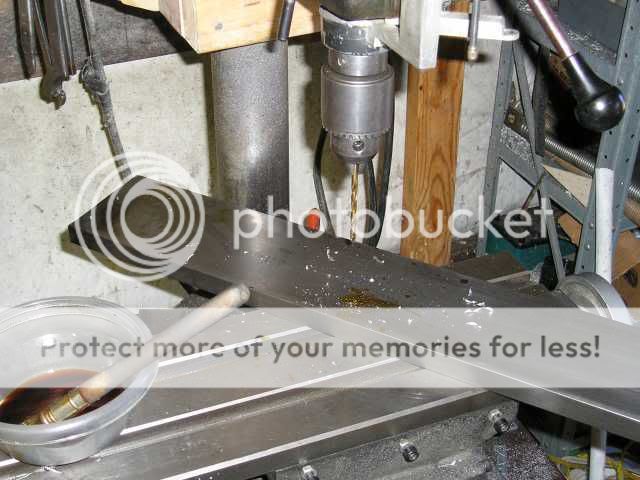
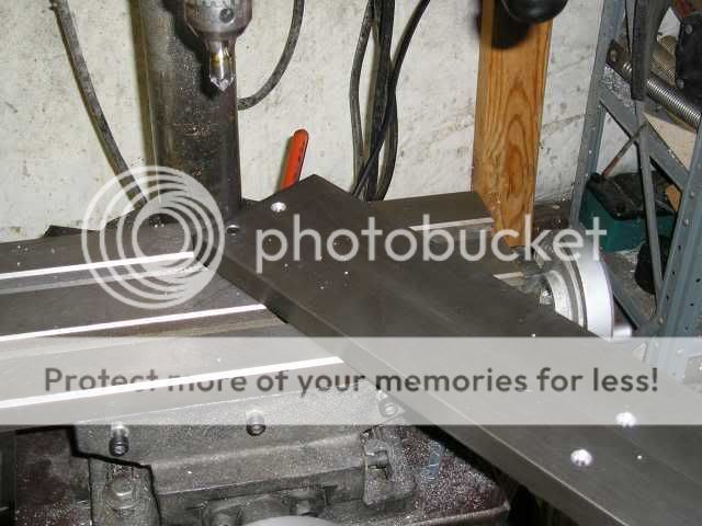
I decided to work on something "easy", so I started to lap my cross blocks. The picture of the milling operation above is a little deceptive..the flash masked the milling marks (though you can see them plainly in the pic with the screws). I lapped the blocks on a piece of oiled 220 grit sand paper just enough to smooth the marks...

The lapped block is on the left, and an unlapped block is on the right for comparison. I will sand the rails as well, and then I will lap the blocks to the rail with some 1200 grit lapping compound prior to assembly.
Casey
I decided to work on something "easy", so I started to lap my cross blocks. The picture of the milling operation above is a little deceptive..the flash masked the milling marks (though you can see them plainly in the pic with the screws). I lapped the blocks on a piece of oiled 220 grit sand paper just enough to smooth the marks...
The lapped block is on the left, and an unlapped block is on the right for comparison. I will sand the rails as well, and then I will lap the blocks to the rail with some 1200 grit lapping compound prior to assembly.
Casey
I made some progress tonight...I finished lapping 1 set of cross blocks...
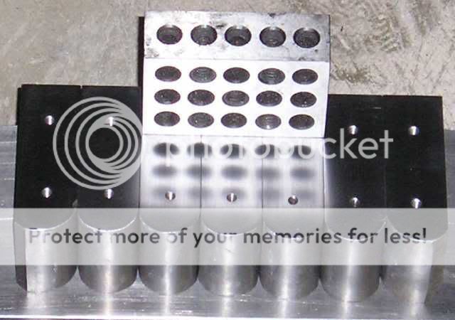
The block on top is to show the reflection provided by the finish. It took 7 sheets of 9" x 11" 220 grit sand paper, a pint of cutting oil, and about 4 hours total to get this finish.
The plan now is to layout and drill 1 side rail, then lap the blocks to both rails with 1200 grit lapping compound (after "roughing" the rails in with yet more 220 sandpaper), securing one side with the screws, and welding the blocks to the other rail. After that I will weld 1" angle iron to both rails for mounting, then square off the ends by putting the whole assembly in my saw.
I figure that with all the tedium involved with prepping the blocks, I can use the motivation of seeing 1 finished magnet assembly to motivate me to finish the second set
Casey
valveitude said:The plan now is to layout and drill 1 side rail, then lap the blocks to both rails with 1200 grit lapping compound (after "roughing" the rails in with yet more 220 sandpaper), securing one side with the screws, and welding the blocks to the other rail. After that I will weld 1" angle iron to both rails for mounting, then square off
Casey
Many ribbon builders find it difficult to precisely position the magnets on the pole steel. Alignment tools that use leverage to move the magnets into place can do less damage to the thin nickel plating than wack-wack with a hammer. Building each pole with its magnets separately makes the final assembly scary. 3' screw rod at the top and bottom can be used as guides to slide the poles together, and 3' of stacked wood can provide some control of the completed poles from jumping together.
Non-magnetic materials are often used for mounting the ribbon to the baffle to minimize stray fields. Would aluminum be better than angle iron?
Hi LineSource,
I have arguably spent more time thinking through the procedure of bringing the 2 halves together than any other aspect of construction. What I have come up with is in line with what you suggest. First I'm assuming you meant 3" rather than 3' for the initial spread..correct me if I'm wrong here. Anyway, I am going to make a series of plastic blocks that are progressively smaller, and purchase screws that are progressively shorter. I am using flat pan head screws that fit into a countersink on the hole. This will register the alignment. I'll start with 3" blocks then "tap" as opposed to "whack" the rails into alignment, and screw in the longest screws. I'll then set in the next smaller set of blocks, and remove the larger ones allowing the free rail to slide down the screws onto the smaller block. I replace the screws with the next set of shorter screws, and repeat this process until the rail mates with the cross blocks. I will probably go with half inch increments until around an inch or so to go, then 1/4" increments till 1/2" to go, then 1/8" for the final increments. I don't consider this optimum, but I believe this will work. I will have some 3/4" "safety" blocks along the magnet gap to prevent the magnets from contacting if something were to go wrong.
I could be wrong of course, but in this case I feel steel is better for 2 reasons. One, I feel more comfortable with the strength of steel with the mass involved, and two, the operative here is stray magnetic field. I believe any magnetism the mounting iron would have, would have been air borne otherwise, I don't believe it would "steal" any flux from the gap, rather it would localize what would have been "floating".
Casey
Building each pole with its magnets separately makes the final assembly scary. 3' screw rod at the top and bottom can be used as guides to slide the poles together, and 3' of stacked wood can provide some control of the completed poles from jumping together.
I have arguably spent more time thinking through the procedure of bringing the 2 halves together than any other aspect of construction. What I have come up with is in line with what you suggest. First I'm assuming you meant 3" rather than 3' for the initial spread..correct me if I'm wrong here. Anyway, I am going to make a series of plastic blocks that are progressively smaller, and purchase screws that are progressively shorter. I am using flat pan head screws that fit into a countersink on the hole. This will register the alignment. I'll start with 3" blocks then "tap" as opposed to "whack" the rails into alignment, and screw in the longest screws. I'll then set in the next smaller set of blocks, and remove the larger ones allowing the free rail to slide down the screws onto the smaller block. I replace the screws with the next set of shorter screws, and repeat this process until the rail mates with the cross blocks. I will probably go with half inch increments until around an inch or so to go, then 1/4" increments till 1/2" to go, then 1/8" for the final increments. I don't consider this optimum, but I believe this will work. I will have some 3/4" "safety" blocks along the magnet gap to prevent the magnets from contacting if something were to go wrong.
Non-magnetic materials are often used for mounting the ribbon to the baffle to minimize stray fields. Would aluminum be better than angle iron?
I could be wrong of course, but in this case I feel steel is better for 2 reasons. One, I feel more comfortable with the strength of steel with the mass involved, and two, the operative here is stray magnetic field. I believe any magnetism the mounting iron would have, would have been air borne otherwise, I don't believe it would "steal" any flux from the gap, rather it would localize what would have been "floating".
Casey
valveitude said:I'm assuming you meant 3" rather than 3' for the initial spread..correct me if I'm wrong here.
I used 3 feet of screw rod with screw nuts and wood spaces to control the joining of the two pole pieces. I was scared when I rough calculated that two 0.15m^2 pole steels magnetized to 0.5T can generate 20,000 Newtons of force as they join.
Force between two nearby attracting surfaces of area A and equal but opposite magnetizations M
F = (uAM^2)/2
where
A is the area of each surface, in m2
M is their magnetization, in ampere/m.
ì0 is the permeability of space, which equals 4ð x 10-7 tesla∙meter/ampere
I used 3 feet of screw rod with screw nuts and wood spaces to control the joining of the two pole pieces. I was scared when I rough calculated that two 0.15m^2 pole steels magnetized to 0.5T can generate 20,000 Newtons of force as they join.
Color me corrected
 ...and a little more concerned. I was "calculating" my initial spread on my observations playing with the magnets. Now that I see the numbers, I'll have to give this some more thought. I think I understand your screw jack arrangement, could you post a sketch?
Casey
LineSource-
After a few hours to let those numbers sink in (I used Convert to translate Newtons into pounds of force to help my hopelessly SAE brain wrap around it), and a couple more thinking about your screw jack idea, I have decided that this is a much better approach..thank you for the "heads up". I have formulated a plan to implement it, so a sketch isn't needed, but I was wondering if you still believe a full 3 feet is necessary. I was thinking 18" should be enough if one half is firmly clamped down, and I had an extra set of hands to guide the 2nd piece onto the threaded rod. It would also accommodate my assembly space a lot better than 36". You've done it and I haven't , so I am all ears.
Casey
Hi Casey,
I already had cheap soft steel 3ft threaded rod. so this was both the easiest and safest path for me. I assembled the poles horizontally on the garage floor, so I did not try to lift and drop one heavy steel pole onto the steel rod, just slid it along the floor until it hit the first wood stop where the threaded rod started into the pole steel. Some scrap wood spacers provided enough extra protection at the start, and also to take some force off the threaded nuts to avoid stripping as I wound them down. I cut one piece of wood to create two inclined planes that together were thicker than the gap when bolted tight, but could go smaller than the gap as they were slid apart. At this point I worked to get all of cross support screws in place for the final run down as the two incline planes were pushed apart and then taken out of the gap. This scratched the magnet plating, so you may have a better solution.
If I was to use a shorter threaded rod I would probably spend more time playing with a wood top clamp/stop to make sure one pole could not hop up, but only slide along the floor. Two people would add safety and muscle.
I tested this assembly before I mounted any magnets to make sure all the screw threads were easy to start and deep enough.
Mounting of magnets
Hi
I have build a set of one meter ribbon drivers using three rows of magnets to mount two strips of ribbon which was then used in series to give me an impedance of .5 ohms.
I useds 3 mm sheetmetal as a backplate and a aluminium faceplate and two pieces of superwood 10 mm thick between the magnets which I glued to the backplate. Once the glue had set I simply removed the wood spacers.
In my first attempt I used a metal faceplate and made the following "discoveries":
a) With a metal face plate the ribbons assembly became a lightning fast guillotine.
b) The metal face plate reduced the magnetic force field so I had redone in aluminium.
c) If the metal back plate is to thick or wide it also reduces the magnetic force field - so keep it as small as possible.
d) With a meter long ribbon with no ribbon support the sound was the most incredible I have ever heard but you could not play it very loud or the ribbon foil would move outside the magnetic force field area. So you need to provide "ribbon support".
e) I used 60 watt class A amps (Stan Curtis design) to drive the ribbons using an basic 12 db (big mistake at the time) active crossover. Listening at night (in the dark) I would get carried away and turn up the volume only to find that a unexpected cresendo would cause a meter long flash as the amps vapourised the ribbon and then a deathly silence would follow....
The effort to replace the ribbon eventually killed this project and I converted to commercially made ribbons.
I still have the ribbons but I still need to revive them using a Behringer digital crossover which I suspect will give me more leeway with crossover options.
If there is interest I will post a picture.
Jozua
Cape Town
South Africa
Hey LineSource,
Thanx for the explanation. I too base a lot of how I do things on what I have on hand, and if I had a floor for assembly I wouldn't bother cutting the rod either. My big shop is a metal shop, and my magnets will never see inside it...I can just see the filings launching out of every nook, and cranny to land on them. After the magnet frames are completed, the 2 halves will be dissassembled, and after a thorough cleaning will be brought into my electronic shop in my house for final assembly. I have some ridiculously strong aircraft aluminum blocks that I will fabricate the jack plates out of that will bolt in place of the end caps. I will use 2 rods per side for a stable "box" of support. The 4 rods will hold the sides apart, and the blocks will only be between the magnets as a safety net in case something fails. I will bolt one rail down to the bench, and jack the other side in horizontally.
Hi Jozua,
No time like the present
I'm always interested in seeing others efforts.
Casey
I already had cheap soft steel 3ft threaded rod. so this was both the easiest and safest path for me. I assembled the poles horizontally on the garage floor, so I did not try to lift and drop one heavy steel pole onto the steel rod, just slid it along the floor until it hit the first wood stop where the threaded rod started into the pole steel.
Thanx for the explanation. I too base a lot of how I do things on what I have on hand, and if I had a floor for assembly I wouldn't bother cutting the rod either. My big shop is a metal shop, and my magnets will never see inside it...I can just see the filings launching out of every nook, and cranny to land on them. After the magnet frames are completed, the 2 halves will be dissassembled, and after a thorough cleaning will be brought into my electronic shop in my house for final assembly. I have some ridiculously strong aircraft aluminum blocks that I will fabricate the jack plates out of that will bolt in place of the end caps. I will use 2 rods per side for a stable "box" of support. The 4 rods will hold the sides apart, and the blocks will only be between the magnets as a safety net in case something fails. I will bolt one rail down to the bench, and jack the other side in horizontally.
Hi Jozua,
I still have the ribbons but I still need to revive them...
No time like the present
If there is interest I will post a picture.
I'm always interested in seeing others efforts.
Casey
It made for a 12 hour day, but I pretty much got to where I thought I should be last weekend.
Since I didn't layout each cross block for drilling, setting up a jig instead, I knew there would be some variance in the location of the screw holes. I also know errors tend to stack up, so I decided to “reset” my baseline by measuring the “center to edge” of each blocks holes before I laid out the side rail...
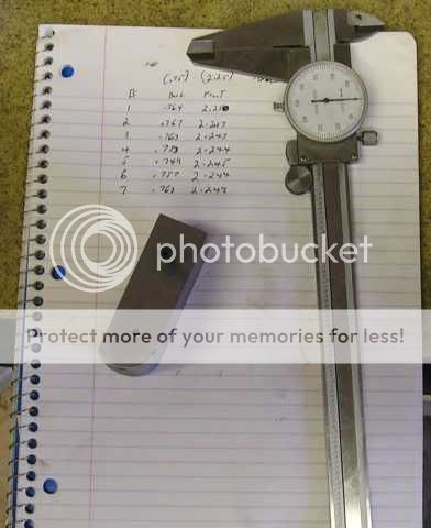
As it turns out, it was a good move. My holes varied +.017” to -.007”. Not a terrible divergence from the target, but beyond the tolerance of the through hole size of .18” (the 8-32 screws have a diameter of .163” leaving a margin of .017” total). With my chart in hand I laid out the side rail for drilling, scribing and punching the screw locations. I then spot drilled all the locations...
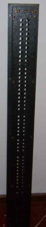
This is where the only error of the day occurred..and it was a doozy. When you punch metal, the material that is moved to make the hole pushes up a ridge around the new hole. On the drilling location for the back hole of block B-3, the spot drill rolled out of the hole onto the outside edge of this ridge, putting the start hole approximately .05” out...damn. This has only happened to me twice before. Oh well, something to fix later. After spotting the locations, I drilled the through holes...
I then test fitted the blocks...
As predicted my botched B-3 hole didn't line up..all the rest where a bullseye. I then fitted my rotary tool with a 1/8” spiral cutting tool, and removed enough material to line up the hole, ending up with a oval. Once i was satisfied with the fit, I then drilled a countersink on the other side of the rail deep enough so that the fasteners were flush with the rail...
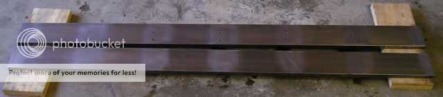
Now we get to the area where I lowered my standard a wee bit. I had originally inteded to lap the rails to the same degree I had the blocks..fuh-getta-bout-it. If I had a an old table saw, I would certainly set up a LineSource surface grinder for this job. After 3 hours of flat blocking with 220 grit paper, I had obtained a nice flat surface, and removed all the scratches from my carbide scribe from the laying out, but I was no where near a true mirror surface. After pondering this a bit, I came to realize that any reluctance at the block-to-rail joints was effectively in series with the ribbon gap. As such, I feel that any loss in the joints would be very small indeed relative to the loss from the .8” gap. If I had a means of getting a “perfect” surface without spending the dozens of man hours necessary to get there with sandpaper I would out of principle. I won't be losing much sleep over it though. Anyway this is what the rails looked like after block sanding for the mating surfaces...
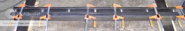
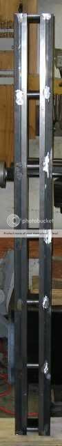
Now is the moment I was looking for a week ago to satisfy my need for gratification..assembly of a magnet frame. I reinstalled all the blocks to the rail with screws, and clamped up the other rail, and trued it up for welding the blocks to the other side...
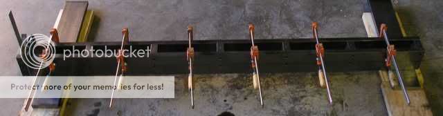
My brothers MIG welder was a little undersized for welding 3/4” stock to 1” stock, and it took making a few ugly joints before getting a good weld. Even then, the welds were sub-optimal..there will be some grinding in my future. After welding the blocks I clamped on the angle iron for the mounting ears for welding...
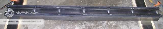
This went a lot better. The 3/16” angle iron responded much better to the welder. After welding this piece, I put a piece on the other side. An almost done magnet frame...
I still need to cut off the ends square, and clean up the welds. I hope to get this done today. If I do I will post the results later tonight.
Casey
Since I didn't layout each cross block for drilling, setting up a jig instead, I knew there would be some variance in the location of the screw holes. I also know errors tend to stack up, so I decided to “reset” my baseline by measuring the “center to edge” of each blocks holes before I laid out the side rail...
As it turns out, it was a good move. My holes varied +.017” to -.007”. Not a terrible divergence from the target, but beyond the tolerance of the through hole size of .18” (the 8-32 screws have a diameter of .163” leaving a margin of .017” total). With my chart in hand I laid out the side rail for drilling, scribing and punching the screw locations. I then spot drilled all the locations...
This is where the only error of the day occurred..and it was a doozy. When you punch metal, the material that is moved to make the hole pushes up a ridge around the new hole. On the drilling location for the back hole of block B-3, the spot drill rolled out of the hole onto the outside edge of this ridge, putting the start hole approximately .05” out...damn. This has only happened to me twice before. Oh well, something to fix later. After spotting the locations, I drilled the through holes...
I then test fitted the blocks...
As predicted my botched B-3 hole didn't line up..all the rest where a bullseye. I then fitted my rotary tool with a 1/8” spiral cutting tool, and removed enough material to line up the hole, ending up with a oval. Once i was satisfied with the fit, I then drilled a countersink on the other side of the rail deep enough so that the fasteners were flush with the rail...
Now we get to the area where I lowered my standard a wee bit. I had originally inteded to lap the rails to the same degree I had the blocks..fuh-getta-bout-it. If I had a an old table saw, I would certainly set up a LineSource surface grinder for this job. After 3 hours of flat blocking with 220 grit paper, I had obtained a nice flat surface, and removed all the scratches from my carbide scribe from the laying out, but I was no where near a true mirror surface. After pondering this a bit, I came to realize that any reluctance at the block-to-rail joints was effectively in series with the ribbon gap. As such, I feel that any loss in the joints would be very small indeed relative to the loss from the .8” gap. If I had a means of getting a “perfect” surface without spending the dozens of man hours necessary to get there with sandpaper I would out of principle. I won't be losing much sleep over it though. Anyway this is what the rails looked like after block sanding for the mating surfaces...
Now is the moment I was looking for a week ago to satisfy my need for gratification..assembly of a magnet frame. I reinstalled all the blocks to the rail with screws, and clamped up the other rail, and trued it up for welding the blocks to the other side...
My brothers MIG welder was a little undersized for welding 3/4” stock to 1” stock, and it took making a few ugly joints before getting a good weld. Even then, the welds were sub-optimal..there will be some grinding in my future. After welding the blocks I clamped on the angle iron for the mounting ears for welding...
This went a lot better. The 3/16” angle iron responded much better to the welder. After welding this piece, I put a piece on the other side. An almost done magnet frame...
I still need to cut off the ends square, and clean up the welds. I hope to get this done today. If I do I will post the results later tonight.
Casey
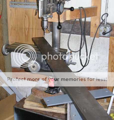
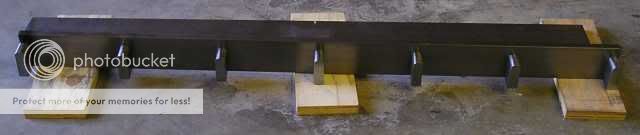
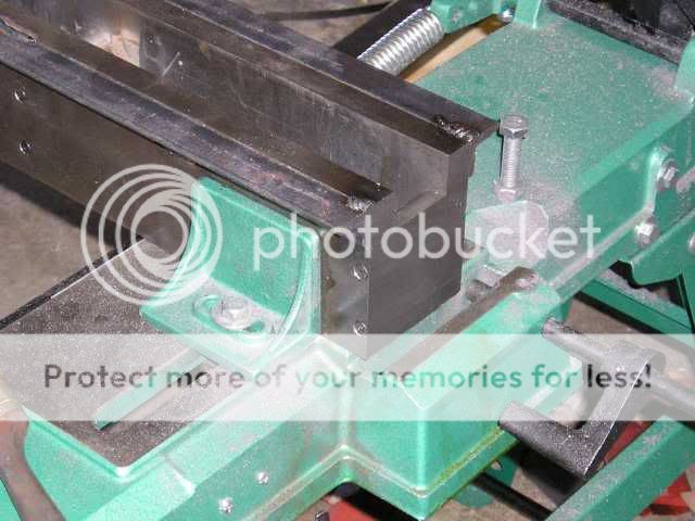
I set up the saw, and tail stand, level and square. I then had my son come over to help me set the frame up on it..did I mention how farging heavy this thing is ? Here is the saw working it's rear off...

About 5 minutes after I took this picture, The blade snapped . it was the same blade that I had used to cut all 14 cross blocks, so it was a little fatigued at this point. I replaced the blade, and finished thecut...
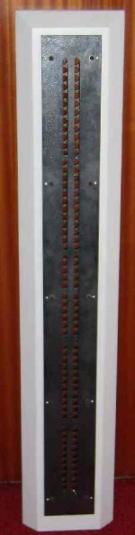
Beauty!! Nice and clean. We flipped it around and cut the other end. It took about 30 min. per cut. I then ground all the welds on the front flush, as well as cleaned up the welds on the sides. I still need to grind the welds on the blocks, but I'll get to that later. I didn't feel like breaking it down just yet. Here is a shot showing the side welds, along with the screws holding the blocks on the removable rail...
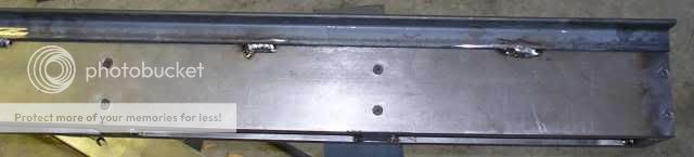
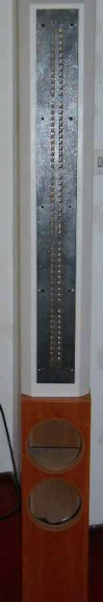
Here is an almost completed ribbon. Missing are the end blocks, magnets, and the mounting holes...
I'm also going to fabricate some handles to bolt to the mounting rails to move this behemoth around..did I mention how heavy it is?
Back to the drudgery of grinding, filing, and lapping the other set of blocks..I am suitably motivated however. Seeing the frame has given this project a sense of the "real" that the collection of the individual components didn't.
Casey
? Here is the saw working it's rear off...
About 5 minutes after I took this picture, The blade snapped
. it was the same blade that I had used to cut all 14 cross blocks, so it was a little fatigued at this point. I replaced the blade, and finished thecut...
Beauty!! Nice and clean. We flipped it around and cut the other end. It took about 30 min. per cut. I then ground all the welds on the front flush, as well as cleaned up the welds on the sides. I still need to grind the welds on the blocks, but I'll get to that later. I didn't feel like breaking it down just yet. Here is a shot showing the side welds, along with the screws holding the blocks on the removable rail...
Here is an almost completed ribbon. Missing are the end blocks, magnets, and the mounting holes...
I'm also going to fabricate some handles to bolt to the mounting rails to move this behemoth around..did I mention how heavy it is?
Back to the drudgery of grinding, filing, and lapping the other set of blocks..I am suitably motivated however. Seeing the frame has given this project a sense of the "real" that the collection of the individual components didn't.
Casey
valveitude said:My brothers MIG welder was a little undersized for welding 3/4” stock to 1” stock, and it took making a few ugly joints before getting a good weld.Casey
Hi Casey,
Welding seems so permanent and final. You are a man who can make a commitment!
I purchased a few rolls of machine slit 5.8 micron aluminun foil before building the pole steel and attaching the magnets. At this point I could make accurate measurements of the magnet thickness in order to precisely cut the rear cross steel spacers which are screwed to both pole steels. I think this sequence allowed me to minimize the ribbon-magnet gaps. High shear strength hex head screws without any counter sinking were used. The ribbons are 90" long and screwed directly to a large aluminun floor base for the main support.
Bolting the steel together allowed me to take it apart a couple years later to switch to a narrower aluminum foil ribbon for better high frequency extension. I just took the hex head screws out of a few cross steel bars at a time and exchanged them with the shorter steel.
Hi LineSource,
Damn The Torpedoes!!
Seriously though, I landed on the .75" width for the ribbon (.8" gap) after a lot of consideration of both what I have observed first hand, a considerable amount of research, as well as the reports of others (I believe you are running .7"..correct?). Of course nothing is absolutely certain with our obsession, and I may very well have erred in some way. If I decide I need to trade off surface area for greater dispersion, I'll figure out a way to grind the blocks down. I can still remove 1 rail, the one with screws. Alternately, I can add spacers if needed.
I am approaching the magnet gap from the opposite direction. I found a suitable donor film/foil capacitor on FleaPay, and purchased a dozen of them. Each cap has enough 8 micron foil for 4 ribbons. At first I was reluctant to go this route, but after playing with one of the capacitors I found it was fairly easy to cut an accurate strip. Basically I will be matching the foil to the gap, rather than the gap to the foil. My first attempt will be to have a .025" gap on either side of the foil. This should be enough to cover any thickness irregularities of the magnets. I will probably attempt a narrower gap after I've lived with them a while.
Casey
Welding seems so permanent and final. You are a man who can make a commitment!
Damn The Torpedoes!!
Seriously though, I landed on the .75" width for the ribbon (.8" gap) after a lot of consideration of both what I have observed first hand, a considerable amount of research, as well as the reports of others (I believe you are running .7"..correct?). Of course nothing is absolutely certain with our obsession, and I may very well have erred in some way. If I decide I need to trade off surface area for greater dispersion, I'll figure out a way to grind the blocks down. I can still remove 1 rail, the one with screws. Alternately, I can add spacers if needed.
I am approaching the magnet gap from the opposite direction. I found a suitable donor film/foil capacitor on FleaPay, and purchased a dozen of them. Each cap has enough 8 micron foil for 4 ribbons. At first I was reluctant to go this route, but after playing with one of the capacitors I found it was fairly easy to cut an accurate strip. Basically I will be matching the foil to the gap, rather than the gap to the foil. My first attempt will be to have a .025" gap on either side of the foil. This should be enough to cover any thickness irregularities of the magnets. I will probably attempt a narrower gap after I've lived with them a while.
Casey
Making your own ribbons
ValveItude
Your design and metal work looks very impressive. I wish I had access to your tools.
My gut feeling is that the steel you using is to thick and will cause a significant loss in magnetic power from the magnets.
I found that I had to make quite a few ribbons so your stock of 4 caps is not going to last long. I went to a aluminium manufacturer and bought sheets of aluminium foil of various thickness until I found what I thought worked best.
I used a very thin layer of Kapton foil "sellotape" (used as isolation material in electrical motors) which I stuck to the back of the ribbon to give it strength. The commercial manufacturers use Mylar. Once it was glued on it also simplied the process of cutting (very tricky process) the ribbon out of the sheet.
If you dont support the foil once mounted you will find that the ribbon movement/tension (which can be quite severe!) will cause hairline cracks to start developing across the "ribbon" and eventually it will simply break.
It all looks simple but believe me it is not.
Regards
Jozua
South Africa
- Status
- This old topic is closed. If you want to reopen this topic, contact a moderator using the "Report Post" button.
- Home
- Loudspeakers
- Planars & Exotics
- A 60" Ribbon w/TL Loaded Extremis Hybrid