To all guys who are building this amplifier,
How do you know that the Step driver is working in your amplifier??
Because even if it is not working the amp will keep running in class_AB mode and you will never know what is happening.
very nice question sir...,,,
how do we know step drive is working???...
regards
ess
Its strange to see that apex didn't mentioned about the testing procedure of this amp, this is not a simple class-AB in which you feed a signal and music comes at output and kids start enjoying the show, its class-H and you need to make sure the STEP is working.
I want to see what Apex has to say about this, I will input my 2 cents later on.
I want to see what Apex has to say about this, I will input my 2 cents later on.
Last edited:
Its strange to see that apex didn't mentioned about the testing procedure of this amp, this is not a simple class-AB in which you feed a signal and music comes at output and kids start enjoying the show, its class-H and you need to make sure the STEP is working.
I want to see what Apex has to say about this, I will input my 2 cents later on.
If you can get higer voltage on amp out than MV, step driver work
")
If you can get higer voltage on amp out than MV, step driver work
Exactly,
But tell the procedure to the guys who don't even have an oscilloscope, all they have is a multimeter.
A simple solution:
Feed a 50-100hz sine at input and measure the voltage at output with your DMM and see its more than Low rail voltage and touching the high rail voltage or near to it. Its just an approximation of its working.
If clip LED light on, output voltage is higer than low rail voltage.
can u pls tel us in details....?
If you use LED instead NSL32, and run amp with 0,+/-55v,+/-110v rail voltage, LED will light on if you have 95v peak voltage on amp out with high level audio input. With low rail voltage of +/-55v, amp will clip at about 50v output voltage, and LED can't light on if step driver not work and not increase rail to +/-110v at peaks.
![APEX%20VERTEX[1].jpg](/community/data/attachments/183/183968-79112707e8285ae1c85fedb3c95c6bbf.jpg)
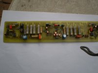
Has any body making H900 ever felt the need of adding more transistors to the output.
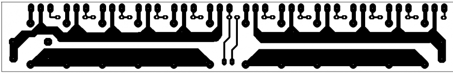
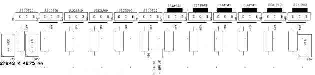
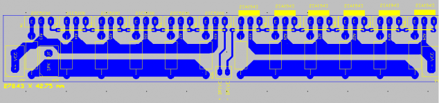
so here it is PCB+ LAYOUT to add 6pairs of additional transistor . and this can used for VERTEX also.
regards
Sekhar
so here it is PCB+ LAYOUT to add 6pairs of additional transistor . and this can used for VERTEX also.
regards
Sekhar
Attachments

Exactly,
But tell the procedure to the guys who don't even have an oscilloscope, all they have is a multimeter.
A simple solution:
Feed a 50-100hz sine at input and measure the voltage at output with your DMM and see its more than Low rail voltage and touching the high rail voltage or near to it. Its just an approximation of its working.
And make sure the hexfet isn't getting blazing hot. If the step is a slow boat to China or "sticking" it may "work" but blow up when the party gets started. You also need to make sure the hexfet stays saturated with a long pulse (low frequency) and under heavy load. You might not be able to verify that very easily under light duty test conditions with just a DMM.
You can build amps without an oscilloscope, but don't blame us if "the roof is on fire" means your amp rack. You don't need anywhere near as expensive of a scope as you do for building class D or SMPS, so I seriously suggest getting one.
TO Mile
Whats the advantage between Ir2117 stepdrive and TL071/72 Step drive?Sound Difference,heat ,stability or what ever?
TY advance
Step driver with IR2117 is simple, stable and safe for HEXFETs (can work without heatsinks), and I suggest this class H step driver for diyers. Adventage is minimum posibility of mistake.
- Home
- Amplifiers
- Solid State
- 900W H-class PA Amp with Limiter