Jan, I finally looked at the links for the amps you have. You are going to need a bunch more amps (assuming you want to drive these to xmax), and you are going to need to be able to supply an incredible amount of power to the amps.
Are you prepared to buy a bunch of amps in addition to all these drivers? Is your wiring and circuits up to this task? We're talking about something like 35000 watts here, to push 4 cabs to xmax (if the drivers will handle it thermally). How serious are you about this? If you can't provide this much power there's no point in using so many drivers.
Are you prepared to buy a bunch of amps in addition to all these drivers? Is your wiring and circuits up to this task? We're talking about something like 35000 watts here, to push 4 cabs to xmax (if the drivers will handle it thermally). How serious are you about this? If you can't provide this much power there's no point in using so many drivers.
Last edited:
Hi j.a.g.,
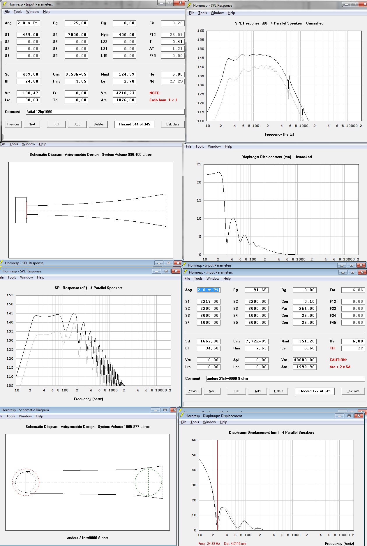
Sorry, I really don't have enough time to play around with Hornresp and folding at the moment, I'm inundated with work, and what I've done so far was just pure procrastination on my part already. Perhaps on the weekend I'll be able to run a sim, can't say for sure. Just one note: You're 4x18 FLH stack requires a 30Hz high pass - my 2x18 TH stack needs a 22Hz high pass. So your design won't go down as far as the graph makes it look. Perhaps we need to establish a lower corner in Hz, how deep OP wants the design to go exactly? As I recall the main problem with the Labhorns was "not deep enough."
Sorry, I really don't have enough time to play around with Hornresp and folding at the moment, I'm inundated with work, and what I've done so far was just pure procrastination on my part already. Perhaps on the weekend I'll be able to run a sim, can't say for sure. Just one note: You're 4x18 FLH stack requires a 30Hz high pass - my 2x18 TH stack needs a 22Hz high pass. So your design won't go down as far as the graph makes it look. Perhaps we need to establish a lower corner in Hz, how deep OP wants the design to go exactly? As I recall the main problem with the Labhorns was "not deep enough."
Hi j.a.g.,
You're 4x18 FLH stack requires a 30Hz high pass - my 2x18 TH stack needs a 22Hz high pass. So your design won't go down as far as the graph makes it look.
This is a good point but this was planned. In fact it will go as low as the graph shows, but the 30 hz high pass will droop the low end down a few db (assuming a low q filter). This is by design, otherwise room gain will likely boost up the low end and it will sound boomy. Even if there is no room gain (which I haven't inquired about yet) OP is no stranger to bass boost with dsp. Also, if a high q filter was used, it could provide a bit of boost before it started to roll off the low end, but that is not my intention either, the droopy low end caused by the high pass filter and the resulting rising response is on purpose. Remember, OP is putting these up against a wall and that's not reflected in these sims, that's going to boost the low end up quite a bit too, in addition to room gain.
Perhaps we need to establish a lower corner in Hz, how deep OP wants the design to go exactly?
We should establish some sort of goals, but some of it will have to be left to individual designer preference. I like to incorporate rising response into the design if it's tuned as low as this, from your previous sim it appears that you don't. Since eq will solve the situation either way (and will likely need to be used to some extent regardless how good the design is) neither design is "right" or "wrong", just different. The main thing is to see how much excursion and power limited spl we can get.
Instead of trying to set rules about where the high pass filter should be set, it would be nice if we could just show our designs with the high pass filters in place. I know this is possible somehow, export the Hornresp record as text and import it into Excel somehow, and manipulate it somehow, but I don't know the details. That would be the best option though.
As I recall the main problem with the Labhorns was "not deep enough."
Yeah, but I think he's hoping for more than just a bit more extension, otherwise he wouldn't be fighting so hard for so many drivers.
Last edited:
Thanks epa, this gives OP much more to look at, more choices, more opinions from different designers.
My one complaint is OP requested 25 hz response, the first horn (flh) can't do it. It needs to be tuned a bit lower.
Other than that, thanks very much. If I could make one request, it would be nice if you could state in your writeup how much power is used, I'm no good at math and don't like doing the conversion from volts to watts. Maybe we should state driver cost as well, but since we are all from different countries that may backfire unless we choose a specific vendor's pricelist to quote from.
Maybe we should set the max cab volume as 1000 liters? That's a nice round figure and I can readjust my sim to match yours. Still waiting for some guidance from OP though, to find out if this is going in the right direction.
Advancing voltage until the excursion limit is hit is standard operating procedure. Excursion limit is a fairly "hard" line, while power limit is over time.Other than that, thanks very much. If I could make one request, it would be nice if you could state in your writeup how much power is used, I'm no good at math and don't like doing the conversion from volts to watts.
Power varies with frequency, in EPA's TH in post # 64 at the voltage input of 96.65 x 96.65=9341.22/3=3113.7 watts at the impedance minima, assuming the minima is the DC resistance.
Most FLH and TH have some frequency that is very close to the DC resistance, a "4 ohm" nominal load can be a problem when it drops to 3 ohms actual. Some amps are forgiving, but certain amps current limit and put out less power below 4 ohms, certain frequencies (musical notes) can drag the sub output down.
Last edited:
I'm sorry, but I'm not sure what you are saying here.
??? Does that mean we normally use enough power to show our graphs at xmax? If so, I know that, if not I have no idea what you mean.
I'm clueless here, which simulation are you referring to? Are you referring to a simulation at all? I don't know what 96.65 x 96.65 represents and why are you dividing that by 3?
I appreciate your help but I have no idea what you are talking about (except for the second sentence and the first part of the third sentence).
Advancing voltage until the excursion limit is hit is standard operating procedure.
??? Does that mean we normally use enough power to show our graphs at xmax? If so, I know that, if not I have no idea what you mean.
... at the voltage input of 96.65 x 96.65=9341.22/3=3113.7 watts at the impedance minima, assuming the minima is the DC resistance
I'm clueless here, which simulation are you referring to? Are you referring to a simulation at all? I don't know what 96.65 x 96.65 represents and why are you dividing that by 3?
I appreciate your help but I have no idea what you are talking about (except for the second sentence and the first part of the third sentence).
Hello guys, thanks a lot.. really A LOT!! for all the info so far, it is so much I have to let it sink in.. I really feel I have to put the design-options aside for now and instead dig in to the basics of Hornresp myself.. for me it feels like a chess game.. lots of parameters and strategies that all effect eachother.. indeed.. you really have to think ahead... I am not good at that so I need some time with it... I think a good way to start is copying some of the sims already made by you.. and I'm shure that will generate truckloads of questions.. I'll feel free to ask around here.. I will be back. thanks again..
J.
J.
In my opinion this is the best way for you to proceed and I applaud your desire to learn this stuff for yourself. There's a wealth of info on this forum (and other places around the net). This way even if you don't end up designing it yourself, at least you can look at the proposed ideas and make educated choices.
I don't usually participate in detail like this, sometimes don't visit this forum for weeks at a time, so I might not be around when you come back. In that case you can send me a PM and if I have time I'll come back, if not these other guys can take care of you just fine, there's a bunch of smart guys here.
I don't usually participate in detail like this, sometimes don't visit this forum for weeks at a time, so I might not be around when you come back. In that case you can send me a PM and if I have time I'll come back, if not these other guys can take care of you just fine, there's a bunch of smart guys here.
Last edited:
Yes, we normally use enough power to show our graphs at xmax.Does that mean we normally use enough power to show our graphs at xmax?
... at the voltage input of 96.65 x 96.65=9341.22/3=3113.7 watts at the impedance minima, assuming the minima is the DC resistance...
I'm clueless here, which simulation are you referring to? Are you referring to a simulation at all? I don't know what 96.65 x 96.65 represents and why are you dividing that by 3?
Voltage squared divided by impedance (Re) = power in watts.
EPA's TH simulation in post #64 that I was referring to used a 91.65 volt input (which I typed wrong as 96.65) in to a pair of 6 ohm (Re) speakers wired in parallel, the cabinet is 3 ohms.
91.65 x 91.65 = 8399.7225 divided by 3 (ohms) = 2799.9 watts, 1399.95 watts per driver.
Art
Yes, we normally use enough power to show our graphs at xmax.
Voltage squared divided by impedance (Re) = power in watts.
EPA's TH simulation in post #64 that I was referring to used a 91.65 volt input (which I typed wrong as 96.65) in to a pair of 6 ohm (Re) speakers wired in parallel, the cabinet is 3 ohms.
91.65 x 91.65 = 8399.7225 divided by 3 (ohms) = 2799.9 watts, 1399.95 watts per driver.
Art
Thanks, I get it now. The formula is simpler than I thought.
Last edited:
- Status
- This old topic is closed. If you want to reopen this topic, contact a moderator using the "Report Post" button.
- Home
- Loudspeakers
- Subwoofers
- 8x12" horn sub