Thank you Mr. Pass.
I wanted the constant current was 400mA at the first but now I have changed my mind. I will set it to be 100mA or 200mA that is enough.
Mr. Pass,
I would like you advice me one thing, clould you advice me a bigger transistor for the constant current circuit?")
I wanted the constant current was 400mA at the first but now I have changed my mind. I will set it to be 100mA or 200mA that is enough.
Mr. Pass,
I would like you advice me one thing, clould you advice me a bigger transistor for the constant current circuit?
Take something in a TO-220 package, figure on driving it
with the two diodes to produce 1.3 volts and figure .65
volts across the Emitter resistor, which at 6.8 ohms will
give you about 100 mA. Assuming that the transistor has
at least 50 for current gain, then the bias through the
diodes should be 5 mA or more, which allows you to
determine that value of the resistor which drives the
diodes. Put a heat sink on the TO-220 transistor, and
Bob's your uncle.
Thank you for teaching me about constant current circuit.

Mr. Pass, I want to study in MOSFET but general electronics device books have a few details of MOSFET. Could you suggest me which book is good for studying about MOSFET. I want to design a audio amplifier by MOSFET.
Could you suggest me the diode part number? Because of I'm not skillful in the using of transistor and diode.two diodes to produce 1.3 volts
Mr. Pass, I want to study in MOSFET but general electronics device books have a few details of MOSFET. Could you suggest me which book is good for studying about MOSFET. I want to design a audio amplifier by MOSFET.
If we take the manufacturer's data, we get:
125W maximum dissipation at 25 deg C. case temp
Max chip temp = 150 deg C.
Internal thermal resistance = 1 deg C. / watt
thumbnail calculation:
With a 30 volt supply and a 1 amp bias, the chip would
be 30 deg above case, and the case would maybe be
20 deg above the sink, which would probably be 20 deg
above ambient, which comes out to 95 deg C. with a
25 deg ambient.
That's about as far as I would consider trusting it.
In the spirit of improving even chip amplifiers, I offer this
Eighth Easy Piece for you LM3886 users:
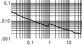
I have noticed that in the distortion curves, there is a little
glitch down at about 1 watt, and that this is a voltage related
glitch, not a current related one (it occurs at twice the wattage
with 4 ohms) and it is consistent.
Eighth Easy Piece for you LM3886 users:
I have noticed that in the distortion curves, there is a little
glitch down at about 1 watt, and that this is a voltage related
glitch, not a current related one (it occurs at twice the wattage
with 4 ohms) and it is consistent.
Attachments
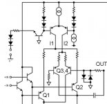
Studying the circuit (or in this case a small section) we can
see the probable cause.
Neglecting the input buffer transistors, the amplifier has two
differential pairs taking feedback. The first, Q1 and Q2 are the
actual signal bearing transistors. Q3 and Q4 form a secondary
pair which does not process input signal (their + input is
grounded) but takes unity gain signal from the output, limited
by a pair of diodes.
When the current is run through the mute pin, Q1,2 are biased
up and Q3,4 are starved for current, so Q1,2 dominate the
performance and everything is normal. When you mute the
amplifier, the current is shifted to Q3,4 and the amplifier goes
into unity gain with a shorted input.
The transition is dependent on the amount of current going
through the mute pin. The spec sheet suggests 500 uA as the
appropriate value, and apparently the distortion curve above
reflects that. But another curve shows the significant sharing
of current between these diff pairs at half this value, and I
suggest that the glitch at 1 watt is an artifact of the incomplete
shutoff of Q3,4 and the diode nonlinearities in that unity gain
loop.
I recommend that you explore higher mute currents at greater
than 1 mA to provide more shutoff to Q3,4 during operation so
as to lower the distortion in the 1 watt region.
The LM3875 does not have this circuit, but the LM3876 does,
and is interesting to note that the mfr's curves do not show this
artifact, although it may be partially obscured by the higher
general THD level in this chip at 1 watt.
Attachments
Thanks Nelson. I noticed the same effect by accident a while back, but I couldn't figure out why it was happening. I find tha 1mA on the mute pin isn't quite enough, and have been using about 3mA finding that it consistently provides a benefit. Now that it has been explained I feel better now that I know I wasn't just deluding myself.
Cheers, Terry
Cheers, Terry
Very interesting.....
Not beeing a shark at math, I tried to calculate the current going through the mute resistor. The mute resistor is connected to the negative rail and output, and I thus count the output as a 0 volt reference - thus, the voltage over the resistor is equal to the negative rail voltage - in my case -33.2 volts, and using a 10K mute resistor - this gives 0,00332 amps.
I notice that other layouts uses higher values like 38K - which gives current values under 1 mA.
Cheers !
Buhl
Excuse me Nelson, but isn't it a change of measurement range of the test equipment?Nelson Pass said:In the spirit of improving even chip amplifiers, I offer this
Eighth Easy Piece for you LM3886 users:
I have noticed that in the distortion curves, there is a little
glitch down at about 1 watt, and that this is a voltage related
glitch, not a current related one (it occurs at twice the wattage
with 4 ohms) and it is consistent.
That's a possibility, although you note that the glitch occurs
at a specific output voltage (1 watt into 8 ohms) and my AP
doesn't do that. A quick thumbnail calculation shows that you
expect the "mute" differential pair to switch in approximately
this region if its bias has not been shut off.
Of course you can always test the proposition by measuring
an actual unit and varying the mute current...
- Status
- This old topic is closed. If you want to reopen this topic, contact a moderator using the "Report Post" button.
- Home
- Amplifiers
- Pass Labs
- 7 Easy Pieces