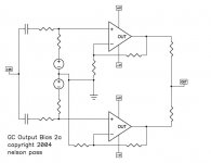
Here we see the same thing as GC-SS-3a, but without the
SuperSymmetry jazz, just a pair of chip amps. The voltage
sources will be low values, as will the output resistors,
and additional output stage is provided by the DC difference
in the output voltages across those output resistors. The
load output sees the split value, so there's no DC seen there.
You also get the advantage of delivering about twice the
current as a single chip amp.
Attachments
Last edited by a moderator:
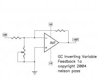
You might find this a trivial circuit, but for those who
don't know it, it can be very important. Chip amplifiers
have enormous amounts of open loop gain (120 dB = 1,000,000)
which can create stability problems when the circuit is set
for low gain, say only 10 or 20 dB. This circuit places a
resistor to ground at the negative input, which throws away
some of the open loop gain, resulting in less feedback. In
fact you can put a variable resistor here, and tune the
amount of feedback to taste.
Attachments
Last edited by a moderator:


Good circuit but incorrect math
The addition of the resistor does not effect the open loop gain
but changes a parameter referred to elsewhere as the noise gain.
This is the closed loop gain between the + input and output. It seems
counter-intuitive but since the - input is a virtual earth a resistor
between - and ground passes no current and thus does not effect
the input stage in any way (other than if the value is reduced to values
close to zero).
I realize almost everybody finds this highly counter-intuitive
and, as I post this, I doubt even my own certainty. A better mind
than mine might be able to work out the effect of the resistor on
frequency response and distortion.
You might find this a trivial circuit, but for those who
don't know it, it can be very important. Chip amplifiers
have enormous amounts of open loop gain (120 dB = 1,000,000)
which can create stability problems when the circuit is set
for low gain, say only 10 or 20 dB. This circuit places a
resistor to ground at the negative input, which throws away
some of the open loop gain, resulting in less feedback. In
fact you can put a variable resistor here, and tune the
amount of feedback to taste.
The addition of the resistor does not effect the open loop gain
but changes a parameter referred to elsewhere as the noise gain.
This is the closed loop gain between the + input and output. It seems
counter-intuitive but since the - input is a virtual earth a resistor
between - and ground passes no current and thus does not effect
the input stage in any way (other than if the value is reduced to values
close to zero).
I realize almost everybody finds this highly counter-intuitive
and, as I post this, I doubt even my own certainty. A better mind
than mine might be able to work out the effect of the resistor on
frequency response and distortion.
I get dead links on the original Seven Easy Pieces pdfs. Google doesn't point to any alternate sources. Any suggestions.
The articles are those included in the Nelson's #1 post of this thread, cut and pasted below for convenience.
Here's 7 easy pieces for chip amps.
OP-Amp test Inverted Mode & Variable NFB.pdf
You might find this a trivial circuit, but for those who
don't know it, it can be very important. Chip amplifiers
have enormous amounts of open loop gain (120 dB = 1,000,000)
which can create stability problems when the circuit is set
for low gain, say only 10 or 20 dB. This circuit places a
resistor to ground at the negative input, which throws away
some of the open loop gain, resulting in less feedback. In
fact you can put a variable resistor here, and tune the
amount of feedback to taste.
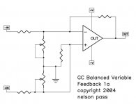
OP-AMP, GC-VAR-BAL-FDBK-1a.pdf
Does the same thing for a balanced input circuit. Generally
you want the pots at equal value, but for the most perfect
common mode input rejection, separate pots allow trimming.
OP-AMP, GC-OUTPUT-BIAS-1a.pdf
You say your chip amp needs more output bias? Here's an old
trick.
OP-AMP, GC-OUTPUT-BIAS-2a.pdf
Here we see the same thing as GC-SS-3a, but without the
SuperSymmetry jazz, just a pair of chip amps. The voltage
sources will be low values, as will the output resistors,
and additional output stage is provided by the DC difference
in the output voltages across those output resistors. The
load output sees the split value, so there's no DC seen there.
You also get the advantage of delivering about twice the
current as a single chip amp.
OP-AMP, GC-BOOTSTRAP-1a.pdf
What? You want your chip amp to behave as if it's seeing a
higher impedance and also deliver more current? You can
parallel chip amps equally, or you can set one up as a
current bootstrap, relieving the load on the first amp,
but also leaving it in control of the signal. Sort of
like power steering. Watch how you set the current gain
of the bootstrap. For this circuit, 50% is a good number.
OP-AMP, GC-BOOTSTRAP-2a.pdf
And of course you can go crazy and use a lot of them. In
this case, the current gain would probably want to be set
to divide the current equally between all the amps, including
the first one. In the case of 4 bootstrap amps, each would
probably want to be set at delivering 20% of the output
current.
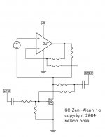
OP-AMP, GC-ZEN-ALEPH-1a.pdf
How can we resist not making a Zen amp with such a current
source? Here we see that the Aleph current source is easily
duplicated by a chip amp.
Cheers...TG
Below are the PDF-Files
Attachments
-
OP-AMP, GC-VAR-BAL-FDBK-1a.pdf5 KB · Views: 143
-
OP-AMP, GC-OUTPUT-BIAS-2a.pdf5.2 KB · Views: 122
-
OP-AMP, GC-OUTPUT-BIAS-1a.pdf4.9 KB · Views: 129
-
OP-AMP, GC-BOOTSTRAP-2a.pdf6.5 KB · Views: 129
-
OP-AMP, GC-BOOTSTRAP-1a.pdf5.3 KB · Views: 124
-
OP-Amp test Inverted Mode & Variable NFB.pdf4.5 KB · Views: 150
-
OP-AMP, GC-ZEN-ALEPH-1a.pdf4.7 KB · Views: 161
Last edited:
check out in this case also post #14 under
https://www.diyaudio.com/forums/sol...pplication-opa2134-opa2604-2.html#post5646479
https://www.diyaudio.com/forums/sol...pplication-opa2134-opa2604-2.html#post5646479
Comparing of THD for a wide range of integrated and discrete Op-Amps:
http://www.nanovolt.ch/resources/ic_opamps/pdf/opamp_distortion.pdf
http://www.nanovolt.ch/resources/ic_opamps/pdf/opamp_distortion.pdf
- Status
- This old topic is closed. If you want to reopen this topic, contact a moderator using the "Report Post" button.
- Home
- Amplifiers
- Pass Labs
- 7 Easy Pieces