Stocker said:Isn't #6 the kissing cousin of my massively parallel small-signal amplifier idea?
I believe they could kiss, but I wouldn't want to see their
offspring.
")
Nelson Pass said:
www.passlabs.com/np/GC-OUTPUT-BIAS-2a.pdf
Here we see the same thing as GC-SS-3a, but without the
SuperSymmetry jazz, just a pair of chip amps. The voltage
sources will be low values, as will the output resistors,
and additional output stage is provided by the DC difference
in the output voltages across those output resistors. The
load output sees the split value, so there's no DC seen there.
You also get the advantage of delivering about twice the
current as a single chip amp.
Funny, I posted the same idea some months ago.
http://www.diyaudio.com/forums/showthread.php?postid=325476#post325476
Steven
lumanauw said:How does GC current bootstrap works?
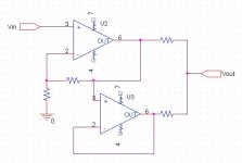
The bootstrap circuit is a lot easier to analyze if you simplify it a little. Pretend you drive it from a single ended source (so GND the -in). Then the first opamp looks just like a non-inverting opamp. The 2nd opamp is a little harder to analyze. Firstly there's the output resistor from the first opamp going into the load, that's probably a current sharing resistor so think something low value. 2ndly you see that the RF2 for the bootstrap opamp ties into the same thing. I suspect that RF1+RF2 of the 2nd opamp dictate the current sharing with Rout of the first opamp. You'd want their values to be the same yet small. Next you see that there's a positve feedback mechanism on the 2nd opamp but it's through a resistor so it sort of "defers" the + input voltage to the first opamp. Both of these facts lead it to the notion that the 2nd opamp is more like a comparator, all it wants to do is drive HARD towards one rail or the other. Then if you think about what happens if the 2nd opamp tries to drive too hard, the NFB mechanism of the first opamp sees this and tries to correct for it which will affect the way the 2nd opamp behaves.
So in short, what you have is that the 2nd opamp is a "current buffer" for the first opamp but is rigged to be slightly out of control so that the first opamps NFB loop is the dominant factor in the action.
Here's a simplified version... take this and add some PFB around the buffer and change the driver to a diff input and you'll see a similar result. Look at the OPA541 datasheet and you should see a similar circuit (although the figures are mislabeled in it).
--
Danny
Attachments
One more thing.
The reason you can't do what I've shown with GCs is that GCs aren't unity gain stable. So then the real trick to this design is to use the 2nd opamp as unity gain while having it actually have gain. Hence having it connected to the load through the feedback loop as an attenuator.
The reason you can't do what I've shown with GCs is that GCs aren't unity gain stable. So then the real trick to this design is to use the 2nd opamp as unity gain while having it actually have gain. Hence having it connected to the load through the feedback loop as an attenuator.
Re: Re: 7 Easy Pieces
So you did. (I don't read the chip amp forum, so I missed it).
Of course the idea wasn't original, as I've pointed out elsewhere,
the first I saw something like it was from Jim Bongiorno, many,
many years ago.
Steven said:Funny, I posted the same idea some months ago
So you did. (I don't read the chip amp forum, so I missed it).
Of course the idea wasn't original, as I've pointed out elsewhere,
the first I saw something like it was from Jim Bongiorno, many,
many years ago.
Hi, Azira,
I can understand your example. It is like giving more current, so the load is handled by 2 GC in your example. But you pointed the important thing. GC cannot operate in buffer mode like in this example.Here's a simplified version... take this and add some PFB around the buffer and change the driver to a diff input and you'll see a similar result. Look at the OPA541 datasheet and you should see a similar circuit (although the figures are mislabeled in it).
I still dont understand the 2 resistors from the output from the 2nd GC to its +input and -input. The one to -input understandable as gain factor resistor combined with resistor from -input to output. But the one to +input gives positive feedback? Is the 2nd GC like you said works like comparator, giving output only +rail or -rail? Like classD? How come it works in analog output swing?The bootstrap circuit is a lot easier to analyze if you simplify it a little. Pretend you drive it from a single ended source (so GND the -in). Then the first opamp looks just like a non-inverting opamp. The 2nd opamp is a little harder to analyze. Firstly there's the output resistor from the first opamp going into the load, that's probably a current sharing resistor so think something low value. 2ndly you see that the RF2 for the bootstrap opamp ties into the same thing. I suspect that RF1+RF2 of the 2nd opamp dictate the current sharing with Rout of the first opamp. You'd want their values to be the same yet small. Next you see that there's a positve feedback mechanism on the 2nd opamp but it's through a resistor so it sort of "defers" the + input voltage to the first opamp. Both of these facts lead it to the notion that the 2nd opamp is more like a comparator, all it wants to do is drive HARD towards one rail or the other. Then if you think about what happens if the 2nd opamp tries to drive too hard, the NFB mechanism of the first opamp sees this and tries to correct for it which will affect the way the 2nd opamp behaves.
This circuit is a work in progress towards building a Bootstrapped SuSy GainClone using LM3875 op-amps, based on Nelson's circuit suggestion earlier in this thread. I have simulated it in Spice but I have not built a protoype yet. The sumulations look good, but as we all know, simulation is not the real world. Before I move into building a test circuit, does anyone have any comments on improvements?
Cautionary Note: Although I have given this circuit a good deal of thought, I am not an EE. Use with caution and at your own risk!
Terry
Cautionary Note: Although I have given this circuit a good deal of thought, I am not an EE. Use with caution and at your own risk!
Terry
Attachments
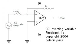
Assume: input resistor is Ri, feedback resistor is Rf, resistor to ground is Rg.
The closed loop gain from input to output is still -Rf/Ri, no changes here. The opamp, however, sees as closed loop gain -Rf/(Ri//Rg), which can be a lot more if Rg is smaller than Ri. So choose Ri and Rf for the desired amplifier gain, then choose Rg for the required minimum closed loop gain for stability.
Look at this circuit as a virtual earth mixing amplifier with two input resistors, Ri and Rg. The input with Ri is your real input; the input with Rg is connected to ground.
Although this circuit improves stability by making the virtual closed loop gain higher, and thus the feedback factor lower, it will also increase noise and distortion with the same factor.
You can improve on that by putting a capacitor is series with Rg to reduce the feedback factor only for high frequencies, where you need it, without increasing the distortion and the noise in the audio band (that much).
Steven
Steven said:You can improve on that by putting a capacitor is series with Rg to reduce the feedback factor only for high frequencies, where you need it, without increasing the distortion and the noise in the audio band (that much).
Yes, although you have to do this quite carefully to avoid
creating an oscillator. When the "apparent" increase in
gain at high frequencies meets the declining open loop gain,
you can get more phase shift than you expected.
Steven said:The closed loop gain from input to output is still -Rf/Ri, no changes here.
OneMoreCupOfCoffee:
Very intersting. Even with Rg, still the non-inverting input could be assumed as a virtual ground. Is it right?
jh6you said:This equivalent circuit explains all.
As a matter of protocol, if you modify my image, you will want
to remove the copyright.
- Status
- This old topic is closed. If you want to reopen this topic, contact a moderator using the "Report Post" button.
- Home
- Amplifiers
- Pass Labs
- 7 Easy Pieces