I see people use tube rectification in this project. From what I understand, theoretically, tubes do not have that "switching noise" of SS diodes that can potentially improve high frequency sonic characteristic of the circuit. What about regulated power supply? Does it make the same noise as regular ss diodes it measurable and can be heard? Any advantages of Tube PSU vs regulated here?
I've already got some rubber decoupling mounts installed on the sockets, so just eeking out some incremental improvements, and some curiosity driving.
Just ordered a pair of metal 6V6's- not terribly expensive so worth a try. Will report back!
Just ordered a pair of metal 6V6's- not terribly expensive so worth a try. Will report back!
Bigger elements and bottle of power tubes vs Noval preamp tubes makes them prone to mechanical feedback when not used as intended i.e. using them for line level instead of power output as we heretically do here. Thus the elastic mounting and hand picking measures we took in gain mode.
The output transformer in a power amp divides their gain by its ratio so they behave well.
Metal ones I haven't had any to test in this preamp so I can't give you a reliable opinion.
 Good luck with them!
Are they totally plug and play compatible? I was reading something about pin 1 needing to be grounded but I'm totally no expert. If so, to earth or gnd? (currently separated by 10R||22nF loop breaker). Also if this is necessary, will the affect anything when going back to glass?
Its only a shield connection for the metal shell directly to chassis. Do that with a short wire somewhere nearby. You don't want long wire inductance to mitigate shell collected RFI dumping to the grounded chassis. But its N.C. (no connection) in the glass versions. So it won't matter to them if left there.
I see, thank you. I accidentally discovered the iron from an old hammond L100. Looks like the power transformer is just right for the job 315V with, but the choke is 14Hy 130R or so, would that work?
Yes why not, seems like a chunky choke. It should not be saturating for inductance yet at the 40mA or so needed here for both signal tubes.
So taking all the parts out of the closet and do some research I found that there were some variations of L-100. The choke is 500r and kinda small in my case. I have no idea how to check the inductance and max current...
The power transformer is 330-0-330 with no load. So that should be fine. Also I have the PSU board from the Aikido seating around with regulated separate filament supplies and Mida HV section. So basically only thing is holding me are tubes and figuring if the choke I have works. Any ideas how I can check it?
One more thing, Salas, what is the final schematics the one hand drawn from post 1 or from the simulator, post 190?
If you use a capacitor input filter for the B+, be real sure to keep the wires short, from the B+ secondary, center tap if there is one, diodes / or bridge, and the first cap (sometimes also to the second cap.
Make a local loop of all those wires.
Regardless of the rest of the amplifier, that transient capacitor current is the largest in the amplifier, and has the most high frequency energy of anywhere in the amplifier.
Failing to take care of that local loop properly, you will have one of the worst sounding ground loops ever.
(No matter the type of rectifier, tube, or solid state).
Just sayin.
@PKI
The LTspice schematic in #190 is the same gain cell as found in the hand drawn full blocks one. Small differences are it shows a resistor between input and ground instead of a volume pot and the screen to plate resistor is 180R instead of 120R but that or the output capacitor's different value doesn't matter for the purpose. It was simulated to see if the voltage points on the real thing were followed with the spice model's application.
The LTspice schematic in #190 is the same gain cell as found in the hand drawn full blocks one. Small differences are it shows a resistor between input and ground instead of a volume pot and the screen to plate resistor is 180R instead of 120R but that or the output capacitor's different value doesn't matter for the purpose. It was simulated to see if the voltage points on the real thing were followed with the spice model's application.
So basically only thing is holding me are tubes and figuring if the choke I have works. Any ideas how I can check it?
Doesn't have a type number to look it up? It takes an LCR meter to know the inductance. At 500Ω it does not seem to be a heavy current part for a big amp but for a preamp it should suffice.
Only LCR meeter I have is the driver tester DATS and it doesn't go that high, who would think, google helped! Thank you hehe.
AO-24159-0 549-6621: 10H - 75mA - 500 ohm Should be ok in terms of max current, right?
Your schematics suggests 220R in total, and arrangement should be RCLC, will CLC with 500R work, or I still will need to add a resistor before the first cap?
AO-24159-0 549-6621: 10H - 75mA - 500 ohm Should be ok in terms of max current, right?
Your schematics suggests 220R in total, and arrangement should be RCLC, will CLC with 500R work, or I still will need to add a resistor before the first cap?
Last edited:
I've already got some rubber decoupling mounts installed on the sockets, so just eeking out some incremental improvements, and some curiosity driving.
Just ordered a pair of metal 6V6's- not terribly expensive so worth a try. Will report back!
Hi Anchan
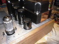
look how i reduce microphonic with fan elastic mounting
6V6 line preamp
10/20 PCS New Durable Screw Pin Rivet Rubber Pc Fan Noise Absorbtion Fans Anti Vibration Mount Silicone Screws Fast Delivery|Screws| - AliExpress
Attachments
Last edited:
Only LCR meeter I have is the driver tester DATS and it doesn't go that high, who would think, google helped! Thank you hehe.
AO-24159-0 549-6621: 10H - 75mA - 500 ohm Should be ok in terms of max current, right?
Your schematics suggests 220R in total, and arrangement should be RCLC, will CLC with 500R work, or I still will need to add a resistor before the first cap?
The mA rating is enough. About total R you will see in combination with your transformer and rectifier tube. If the whole thing goes unnecessarily high for rectified DC under load you may add extra R.
Hi nikosokey, thanks for the link. Looks great! I actually already have the mechanical isolators installed that I linked to and they work great. I can hammer on the chassis, and no sound in the speakers 
Your solution looks like it works well too.
Your solution looks like it works well too.
About to place an order, is this the final schematics? (first post) 6V6 line preamp
That 0.68 output cap, can it value be changed a bit or that value is optimal? I should have some on hands, but not sure I have exactly 0.68?
That 0.68 output cap, can it value be changed a bit or that value is optimal? I should have some on hands, but not sure I have exactly 0.68?
Yes that's the original preamp's full schematic. Had 15.5dB (6X) gain, be very sure you need it. Else consider its times one gain cathode follower version. The output capacitor is to be optimal for your amp's input impedance. That 0.68uF reflects interfacing with a high input impedance KT-88 amp I had at the time.
You would want something around 2Hz -3dB corner frequency. Prefer the 50k Log pot value also. For allowing more HF bandwidth.
You would want something around 2Hz -3dB corner frequency. Prefer the 50k Log pot value also. For allowing more HF bandwidth.
Thank you Salas. So far I am planing to use it with a Rin 47k solid state amp.
I only could find 2x11k KIWAME caps instead of 2x10k as in the schematics is it bad? I see you were saying that you suppose to use regular resistors for low power ones, any disadvantage of using KIWAME everywhere?
I only could find 2x11k KIWAME caps instead of 2x10k as in the schematics is it bad? I see you were saying that you suppose to use regular resistors for low power ones, any disadvantage of using KIWAME everywhere?
11K//11K make 5.5K anode load so still close to the original value. Tubes have tolerances and they are biasing at about same points between samples anyway.
With 47K amp 1.5uF Cout will make 2.56Hz -3dB high pass corner frequency when 2.2uF Cout will make 1.54Hz. Those will keep the phase turn at 20Hz in check.
Kiwame (KOA Speer SPR series in reality) are good all round resistors for this purpose. Riken carbon was better but defunct. Amtrans AMRG is their descendant. Put those for grid stopper and cathode resistors if you can.
- Home
- Amplifiers
- Tubes / Valves
- 6V6 line preamp