5 star repair.D1 felt a little bullied to so it was replaced. Now its set happily to 260 Vout and 40 mA. I thank Metaxa for that one and wave to Zeus")

Thank you. I went over for some more for helping me on the hum part also.5 star repair.
With the Metaxa?
I'm rigging a new testbed for the 6V6. The barge grew out of the costume and it was to messy to know which factor gave what result. This one gonna be more up to modular approach. I'm thinking resistor AF, choke AF, resistor CF, choke CF, ability to go with or without SSHV etc. Its better to let it take some time and think it thru.
I've also been working some on the lab-bench. I noticed that the mV measuring got affected alot on how I held the probes, close to lamps, powercords etc. The bench is prepped with an isolated earthgrounded worktop and shielded AC etc. Ill post some when I have some results.
Last edited:
With the Metaxa?
I'm rigging a new testbed for the 6V6. The barge grew out of the costume and it was to messy to know which factor gave what result. This one gonna be more up to mudular approach. I'm thinking resistor AF, choke AF, resistor CF, choke CF, ability to go with or without SSHV etc. Its better to let it take some time and think it thru.
I've also been working some on the lab-bench. I noticed that the mV measuring got affected alot on how I held the probes, close to lamps, powercords etc. The bench is prepped with an isolated earthgrounded worktop and shielded AC etc. Ill post some when I have some results.
Watch out for fluorescent bench lights !!
I have 2 over by bench and they are very measurable
.Building a separate Modular PSU gives you the benefit of using it for several different amps.
Watch out for fluorescent bench lights !!
Im thinking LED-lights, my halogen and also the scopes phosphor screen is easily measurable several decimeters away
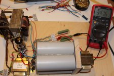
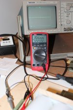
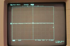
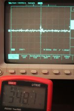
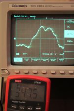
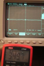
Ok, heres my new CLCLC. Pic one no voltage probes on, pic 2 same closeup, pic 3 full B+ at 2*7500 k load, about 93 mA. Pic 4 mains variations, slower time/div. 10X probe 200 MHz (thank you Siberia) calibrated for the scope. I guess I could run this with neat results on a normal resistor AF.
The step now is just to rule PSU out of the picture if I get strange results on circuits later tho. Seems ok.
The step now is just to rule PSU out of the picture if I get strange results on circuits later tho. Seems ok.
And yes. The PSU chokes are now completely floating. I measured big differences last time on how I connected them. They can be separately connected between shell, with screws to chassie, which made huge differences if or if not last time. There is also a core grounding, which now floats. I will alter this and see what differences it makes. On line chokes it might even be worth to try tie it to filament level. Never know...
At this point I think its pretty perfect for an other split LC, I think I have some at 12ish H 50 mH style. Tho no filaments is plugged in the circuit yet, exept fpt the GZ34, so it might bring down B+ a few volts. Maybe enough for some 310 after dual SSHVs, a bit to low tho for resistor AF. This tranny is super for maybe 150+105 glowtubes and 115 H/930 anode loads.
What do you think of that?
A pair of sand rectifyers will bring it to resistor AF level with SSHVs
What do you think of that?
A pair of sand rectifyers will bring it to resistor AF level with SSHVs
Last edited:
- Home
- Amplifiers
- Tubes / Valves
- 6V6 line preamp