Anyways, this is the new form factor I'm gonna build things in from now on. 43 cm (full rack) deep and 25,5 cm with. I have started to dislike all kinds of various stuff between the speakers, takes an engineer to place stuff out and mix between them.
My next build is a pair o SoZs donut mode (first pure sand build for me). Thats why I suddenly changed my mind on Vout and might go for an anode loader try on the 6V6 also. All my other poweramps has a sensitivity to steer out under 2 V rms. New stuff gonna stick to that, no matter if its dual mono, external PSUs or what.
After that I'm afraid its gonna be a TT. I have found some glorious things from swedish radio that I cant get my mind off. A pair of TTS-3000 tops. I guess it will be 43 deep and 50+ with then, to match")
My next build is a pair o SoZs donut mode (first pure sand build for me). Thats why I suddenly changed my mind on Vout and might go for an anode loader try on the 6V6 also. All my other poweramps has a sensitivity to steer out under 2 V rms. New stuff gonna stick to that, no matter if its dual mono, external PSUs or what.
After that I'm afraid its gonna be a TT. I have found some glorious things from swedish radio that I cant get my mind off. A pair of TTS-3000 tops. I guess it will be 43 deep and 50+ with then, to match
Attachments
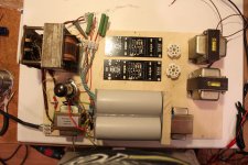
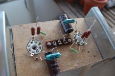
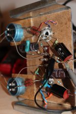
Just a partial update on behalf of that I intend to exclude possible fault sources on the way by building it up in easy steps. So if I exclude SSHVs the 90ish mA total load was to heavy, so I replaced it with dual 13k5s. Then voltage goes up ofc. Pic 1.
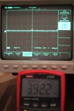
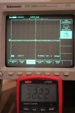
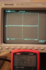
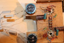
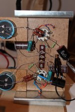
So I serielled dual 3k4 two following RCs. Pic 2 and 3. As you can see it looks flatsy and nice and puts me in the ballbark for a real 5 k resistor anode load test. 323 V over 13k5 gives approx 24 mA. Might soften the last R up a bit to give room for the filament load on the tranny also. Lets see.
But now the Metaxa bell rang. Laters...
/Staffan
Attachments
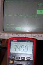
My presssious. So, for the record I configured an anode follower. Its Salas original updated schem, 340 V B+ and 5k anode load.
You guys are prolly laughing pants off as I plugged cathode to wrong pin b4 so I had an open circuit and had 450 V over all the caps. Luckily those are pretty sturdy. Now its on pin 8 as it should be.
Anyways, I just built the circuit as a measuring dummy for now, the intent is just to see if I get the same 50 Hz indications as b4. So I have now 68K instead of pot to gnd and a 10 meg out. Heres the results, measuring (a little highish but anyways) B+. Smooth as a baby rump to me. No signs of 50 Hz as b4.
So, if I sober up any day this week it would be nice to compare FFT values to former measures and go on with a choke loded AF to begin with.
Attachments
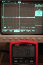
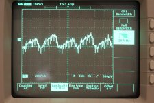
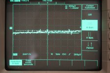
Hard to say, at least not much to brag about. Note that Im yet on AC for filaments. Sorry, forgot to turn off flash, its 5 mS/div. Over the 10 M output:
Is that only 600uV pk-pk? Not perfect but not dreadful either for now.
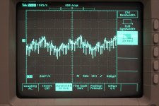
Howdy. Getting some measures I dont quite understand here. Hilfe!
I remeasured B+ over last 220 uF cap, pic 1, probe 10X
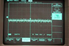
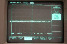
Then I mounted 1 uF caps on the output and moved the 10 M resistor to after that as load. Pic 2 not plugged in, pic 3 over the 10 M. Now probe to 1x
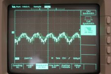
So I loaded it down a bit more with a 120 k over 10 M, pic 4
My guess is that I'm watching floating filament AC. Whats your guess?
I remeasured B+ over last 220 uF cap, pic 1, probe 10X
Then I mounted 1 uF caps on the output and moved the 10 M resistor to after that as load. Pic 2 not plugged in, pic 3 over the 10 M. Now probe to 1x
So I loaded it down a bit more with a 120 k over 10 M, pic 4
My guess is that I'm watching floating filament AC. Whats your guess?
Attachments
-
 new setup 011 (2000x3000).jpg396.7 KB · Views: 113
 -
 new setup 010 (2000x3000).jpg592 KB · Views: 109
 -
 new setup 009 (3000x2000).jpg791.4 KB · Views: 71
 -
 new setup 008 (3000x2000).jpg810.5 KB · Views: 74
 -
 new setup 007 (3000x2000).jpg789.8 KB · Views: 74
 -
 new setup 006 (3000x2000).jpg792.6 KB · Views: 92
Last edited:

Is that only 600uV pk-pk? Not perfect but not dreadful either for now.
The uV thingie is trigger level. I'm not quite familiar with cursors on this scope yet
That is the ~15dB gain common cathode circuit? I also see some EMI like spikes after you opened the loop area further. But the pk-pk remains the same amplitude if dirtier even. Maybe you can use your probe's short ground coil accessory instead of its 5inch crock gnd wire when twisting some circuit gnd extension wire near the output capacitor so to make it a tighter area for what its winding and size can change for the measurement loop. That pk-pk wave looks like its 10mS so its 100HZ. Can you find 50Hz at all at 20mS? Any counter to turn on in the scope so not to count divisions?
Here is cursors. The curves are very probe-positioning dependent tho. We are down to so low levels that everything interferes, even my hands.
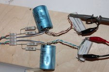
I think I have an OK B+ tho. Well last 220 caps are maybe not state of art but they work and theyre sturdy for experimental work. Ran one backwards on 350 V yesterday and it didnt mind. Have hundreds of them.
I think I have an OK B+ tho. Well last 220 caps are maybe not state of art but they work and theyre sturdy for experimental work. Ran one backwards on 350 V yesterday and it didnt mind. Have hundreds of them.
Attachments
The uV thingie is trigger level. I'm not quite familiar with cursors on this scope yet
OK. It only does show on screen measurements when using cursors? No menu for just showing VRMS, VPP, Freq, Time etc? Still on a 2mV/div it was something like 600-800uV pk-pk deflection as far as I can see in that flashy pic. About two subdivisions?
Yes, in the ballpark your "updated schematic" with 340 v B+, 5k anode load, 680R/1000uF on cathode and 180R anode to g2.That is the ~15dB gain common cathode circuit?
I also see some EMI like spikes after you opened the loop area further. But the pk-pk remains the same amplitude if dirtier even. Maybe you can use your probe's short ground coil accessory instead of its 5inch crock gnd wire when twisting some circuit gnd extension wire near the output capacitor so to make it a tighter area for what its winding and size can change for the measurement loop. That pk-pk wave looks like its 10mS so its 100HZ. Can you find 50Hz at all at 20mS? Any counter to turn on in the scope so not to count divisions?
Did Iko have a pic of that some posts back? Im heading to post office, I think theres a new pair of probes there. Brb!
Here is cursors. The curves are very probe-positioning dependent tho. We are down to so low levels that everything interferes, even my hands.
I think I have an OK B+ tho. Well last 220 caps are maybe not state of art but they work and theyre sturdy for experimental work. Ran one backwards on 350 V yesterday and it didnt mind. Have hundreds of them.
It looks like very tame a B+ considering the practical probing and the 2mV/div self noise, what is possible to pick up from the environment etc.
Did Iko have a pic of that some posts back? Im heading to post office, I think theres a new pair of probes there. Brb!
That was from a very quiet full analog scope after a regulator in speedier dial timing if I remember well. Now you measure a completely passively filtered B+, right?
That was from a very quiet full analog scope after a regulator in speedier dial timing if I remember well. Now you measure a completely passively filtered B+, right?
Yes, its 50uF-10H-50uF-10H-100uF-dualsplit-3k4-220uF
What measurements are you talking about, B+ or output?
- Home
- Amplifiers
- Tubes / Valves
- 6V6 line preamp