If you want to, you could probably also get rid of the second stage of filter caps. The regulator is really good at getting rid of 100-120Hz ripple. They certainly won't hurt anything, though.
Here is a picture of my heatsink, salvaged from an industrial motor inverter. It's overkill.
Here is a picture of my heatsink, salvaged from an industrial motor inverter. It's overkill.
Attachments
Another question:
What do R44 and R45 do?
I also had another thought. You could use a 5U4 to drop a little more voltage to get regulator dissipation down.
Anyway, none of these suggestions are meant to push you to do this a certain way. I'm just trying to open your eyes to some options.
What do R44 and R45 do?
I also had another thought. You could use a 5U4 to drop a little more voltage to get regulator dissipation down.
Anyway, none of these suggestions are meant to push you to do this a certain way. I'm just trying to open your eyes to some options.
Should R17 go to ground?
R17 in theory should go to ground. My latest version of this design has R17 going to the wiper of a pot. The ends of the pot go to + and - 2.2 volts generated by using LED's as zener diodes. Why, to allow nulling out those little offsets that add up in a direct coupled design. It's adjustment drastically lowers the distortion at high output voltages, but may not be needed here.
Should R56 be there?
No.
What do R44 and R45 do?
They are anti-blow-up resistors. If the pot wiper goes open the gate of the mosfet floats. A nano amp of leakage in a coupling cap will put +75 volts on the grids of the output tubes, making then very unhappy!
I'm a bit surprised to see the plates powered by the Miata regulator.
Early on in this multi year project Chris scored a pair of Hammond 300BX power transformers. The unregulated B+ from these would be a bit much for a 25 WPC 6L6GC amp, even by my standards. Chris opted for active regulation over a choke input filter, and this is a wise choice for an AB1 or AB2 amp. A class AB amp likes a low power supply impedance. I will probably build two amps using this design. One will be a monster using a BFC across a typical CLC supply. The other will be a lower powered amp, but I won't know the power supply requirements or its details until I figure out what the amp is.
Why not use the full 400V to supply the first stage?.....As for the full 400V for first stage, I suspect that tubelab first drew it as you describe, I will go back and check...
No, I drew it like it is shown here. My first few itterations of this design had low frequency instability issues, so R24 and C16 were added. They are still present on my latest circuit boards, although in theory they should not be needed. Never got around to testing without the parts.
The mosfet in the regulator is configured as a follower, so as current increases, the 11 Ohm resistor will start dropping voltage when more current is drawn through the regulator. I think that the purpose is to make the regulator short-circuit tolerant.
The 11 ohm resistor is for current limiting and maybe short circuit protection. That is the explanation given in Michael Maida's original paper. I can tell you that even with the resistor in place the mosfet will violently explode if the output is shorted after the circuit is already on. It may offer some protection if the short is present at turn on.
I have been gone all day. I traveled to a hamfest where I got 93 new test subjects including some more 6HJ5's from ESRC, his supply of these tubes is nearly gone. I also got a big box full of assorted used tubes (mostly sweep tubes) for $5. I just got to hook this breadboard up. There is some glow testing to be done.
The 11 ohm resistor is for current limiting and maybe short circuit protection. That is the explanation given in Michael Maida's original paper. I can tell you that even with the resistor in place the mosfet will violently explode if the output is shorted after the circuit is already on. It may offer some protection if the short is present at turn on.
I shorted the regulator in my preamp twice. It's based on the original paper. Both times it instantly blew the transistor, the LM317, the series resistor, and the zener.
...some more 6HJ5's from ESRC, his supply of these tubes is nearly gone.
Dang, and I just ordered some more from him. I guess we'll see if he can actually fill it.
Dang, and I just ordered some more from him. I guess we'll see if he can actually fill it.
I got 20 more 6HJ5's plus about 70 more dollar tubes from Stan at a hamfest on Saturday. He told me that someone had just ordered some, plus my 20, lowered his supply. He had about 200 of them, and said that no one ever buys them, in January.
Thanks everyone for the continued help. I have tidied up the schematic:
R17 to ground instead of the negative supply.
R56 removed.
Questions:
Should I reduce the value of R32, or is the consensus that the 40.2K is OK? I have the 40.2K part already in a TO220 type ready to mount on the heatsink. With 5U4GB (if used) the current through that zenner will be down to under a milliamp...
I think I recall tubelab saying that he had trouble with the IRF820 Mosfets blowing. I had added protection zenners to the MOSFET followers D9 and D10. Are these incorporated correctly?
Good Point about the 5U4G rectifier dropping more volts. Chassis space is tight and the ones I have are the big-bottle style... Also a consideration, is a direct-heated cathode a problem with faster B+ application? Bias supplies are solid state rectified, but have VR tube rectification. Not sure how long the VR tube takes to come on. In any case, I have quite large heat sinks ready for the regulator and pass MOSFET.
With 400V transformer CRC 110u/100R/110u and 180mA, PSU II is showing about 485v with 5AR4 and 433v with 5U4GB. The Hammond transformers do run over-voltage however, so expecting that the voltage to be dropped by the regulator will probably be more like 100v for 5AR4 and 50v for 5U4GB
I like the idea of the resistors to protect against an open wiper.
chrish, it's your call on the 40.2K. I think it will work, but Jones is right that noise on the gate of that mosfet will be lower with more current.
As for the zener, I have been putting back to back zeners to the other side of the stopper (since I have the stopper hooked directly to MOSFET pin and zeners are on a circuit board). I don't know what is better, zener tied to gate pin or the other side of the stopper.
VR tubes come on quick since they don't have a heater/filament. They are cold cathode tubes.
I think you are wise to assume that your output voltage will be a bit higher with the Hammond transformer.
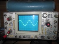
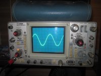
I hope nobody minds the off-topic but we have been discussing George's universal driver here. I just wanted to show some early results with 6SN7 at 780V supply and 10M90S cascode plate loads. It is 200V/div with the 100X probe here. Is this enough for G2 sweep tubes or do they need more?
Attachments
Thanks for taking the time to answer my questions, I really appreciate it!
I have been planning chassis layout and assembling the power supply, no soldering yet, just organising the parts on some perf board. I figure I have plenty of Amps available from the transformer, so opted to follow Jones' advice, used a 12K in that spot.
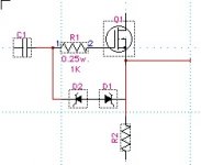
Not quite sure what you are describing re the zener protection of the MOSFET, but I think it is as per the attached image...
I did some measurement of the Hammond transformer for some accurate PSUII modelling. Unloaded voltage was 436VAC, the secondaries were 48R and 50R, primaries 6.5R. PSUII calculated a voltage of 499 volts when loaded with about 180mA (99 volts to drop in the regulator, close to estimation). I will try with a 5AR4, then if the voltage turns out to be too high and things are getting a little warm, I will try a 5U4G.
When I am sure I have the right setup for protection zeners, I will re-post the schematic.
Hopefully I will have the power supply ready to test tomorrow. I am assuming that since I have about 8mA passing through the voltage set divider in the reg (data sheet says 5mA min), I should be able to test it with no other load to confirm it is working OK?
Regards,
Chris
I have been planning chassis layout and assembling the power supply, no soldering yet, just organising the parts on some perf board. I figure I have plenty of Amps available from the transformer, so opted to follow Jones' advice, used a 12K in that spot.
Not quite sure what you are describing re the zener protection of the MOSFET, but I think it is as per the attached image...
I did some measurement of the Hammond transformer for some accurate PSUII modelling. Unloaded voltage was 436VAC, the secondaries were 48R and 50R, primaries 6.5R. PSUII calculated a voltage of 499 volts when loaded with about 180mA (99 volts to drop in the regulator, close to estimation). I will try with a 5AR4, then if the voltage turns out to be too high and things are getting a little warm, I will try a 5U4G.
When I am sure I have the right setup for protection zeners, I will re-post the schematic.
Hopefully I will have the power supply ready to test tomorrow. I am assuming that since I have about 8mA passing through the voltage set divider in the reg (data sheet says 5mA min), I should be able to test it with no other load to confirm it is working OK?
Regards,
Chris
Attachments
I've read that they start regulating about there, but don't freak out if it doesn't. It should be regulating by 10mA I think.
I'm sure Tony is right and they should be tied directly to gate, but I have found it difficult to solder two things directly to the pin of a mosfet that is not on a circuit board. Gets messy. If you can make it work, do it.
I'm sure Tony is right and they should be tied directly to gate, but I have found it difficult to solder two things directly to the pin of a mosfet that is not on a circuit board. Gets messy. If you can make it work, do it.
I had the recent experience of blowing these FETS in a similar set-up. The zeners should tie directly to the gate after the gate resistor. Or use a FET with the diodes built in. i.e. 2SK3563 or a 2SK3564 for higher voltages. IMHO I would think the later two solutions would provide the least capacitance and is certainly easier to implement in a P2P.
Based on a solution that I used in my design, I reduced the resistance of R54, and R55(per your schema). If you took these to 250k, you would reduce (not eliminate) the chance that the gate will exceed its limits wrt the source duing the power up and power down cycle. In any case you would be less reliant on the zeners. I don't know what it would do to your gain structure however.
Based on a solution that I used in my design, I reduced the resistance of R54, and R55(per your schema). If you took these to 250k, you would reduce (not eliminate) the chance that the gate will exceed its limits wrt the source duing the power up and power down cycle. In any case you would be less reliant on the zeners. I don't know what it would do to your gain structure however.
Last edited:
Thanks SpreadSpectrum and others. I have redrawn the schematic with back to back 15V zeners to gate. I will be constructing a mini-board with perf board for these, so I should be able to go straight to the pin.
Thanks SGregory. I might leave the values as designed for now, but if I start blowing MOSFETS, I will take your advice. Had a look at your design. Looks nice, some similarities here... I like your build too, looks well laid out and tidy. I note you have CCS for the MOSFET followers. I did not see the discussion regarding the benefit of their inclusion. Any chance you could spare a few words regarding the expected benefits?
Thanks again everyone for your continued support!
Chris
Attachments
Last edited:
Work has begun...
Spent a few hours going over posts today, as I could not remember why some values of components were chosen. I have reviewed the VR tube supplies, I think I mis-calculated the current limiting resistors there. Also looking at the anode load resistors of the LTPs, they require some high wattage types. I am not sure if I have the right types for these. Murphy says you discover these things at 5pm on the day before Easter, won't be able to get parts till tuesday next week.
Chassis construction has begun. The top plate is 7mm thick, so I am attempting to mount the tube sockets from underneath and tapping the thread for the bolts directly in to the top plate. Hopefully this will have the top plate free of nut-heads showing.
Had an issue drilling the holes for the tubes, I had to get a bi-metal 27mm hole saw. Tried it on a scrap of perf-board and it made the right size hole. After drilling the top plate, I find that it is not perfectly round and it is drilling a 28mm hole. The valve bases will hide the sloppy fit, but I am not happy. Ended up buying a 27mm Starrett 27mm bimetal hole saw for the second chassis. Hopefully it will work out better.
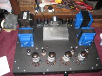
Here are some shots of how the chassis layout looks. Heatsink for the Maida regs is on the back plate.
Note, photo is of top plate only, it is sitting on an MDF jig I made to hold in place when inverted for easier wiring etc.
Cheers,
Chris
Spent a few hours going over posts today, as I could not remember why some values of components were chosen. I have reviewed the VR tube supplies, I think I mis-calculated the current limiting resistors there. Also looking at the anode load resistors of the LTPs, they require some high wattage types. I am not sure if I have the right types for these. Murphy says you discover these things at 5pm on the day before Easter, won't be able to get parts till tuesday next week.
Chassis construction has begun. The top plate is 7mm thick, so I am attempting to mount the tube sockets from underneath and tapping the thread for the bolts directly in to the top plate. Hopefully this will have the top plate free of nut-heads showing.
Had an issue drilling the holes for the tubes, I had to get a bi-metal 27mm hole saw. Tried it on a scrap of perf-board and it made the right size hole. After drilling the top plate, I find that it is not perfectly round and it is drilling a 28mm hole. The valve bases will hide the sloppy fit, but I am not happy. Ended up buying a 27mm Starrett 27mm bimetal hole saw for the second chassis. Hopefully it will work out better.
Here are some shots of how the chassis layout looks. Heatsink for the Maida regs is on the back plate.
Note, photo is of top plate only, it is sitting on an MDF jig I made to hold in place when inverted for easier wiring etc.
Cheers,
Chris
An externally hosted image should be here but it was not working when we last tested it.
An externally hosted image should be here but it was not working when we last tested it.
Between domestic issues and university study, I have managed to spend a little time on this. I am only building one at the moment, after the inevitable trouble-shooting will build its twin.
I have completed the heater wiring, mounted the transformers and built three small perf board sub-assemblies. The one at the rear is, not surprisingly, the power supply. 400V regulated, +150V and -150V. The mid board has the MOSFET followers and bias adjust, as well as a couple of the load resistors for the second diff amp. Front board has the CCS and load resistors and power supply decoupling cap for the first diff amp stage. CCS and MOSFETs are attached to the (7mm thick) top plate for heatsinking. I was going to attach to the sides of the chassis initially, but wanted to go for a no screw head showing look and side walls were not thick enough for a blind tap.
Have not tested the power supply yet. As it is significantly more complex than previous power supplies I have built, I wanted to have it attached to the chassis and heat sink and have the mains supplied from a proper IEC connector with fuse. This is for safety and to try to avoid screw ups and subsequent smokey moments with dodgy alligator clip setups.
Hope to have the mains supply and switch connected up tomorrow. Fingers crossed I did not screw up the point to point wiring of the regulated supply. It was a bit of a pain in the neck to make on perf board. I should learn how to design and fabricate printed circuit boards!
Will keep posted on further updates.
Cheers,
Chris
An externally hosted image should be here but it was not working when we last tested it.
Did the mains wiring today. The +/- 155 volt supplies are working, yet to be connected to their respective voltage regulator tubes. The regulated 400 volt supply is putting out around 445 volts. There is no load at the moment, so their is just the 8-10mA through the set resistors, plus a mA or two through the heater reference lift voltage divider. I see Spreadspectrum's advice above to not worry if it is not regulating with no load. At least there was no smoke! Voltage at the second power supply capacitor after the diode was 575 volts, so it is dropping about 130 volts with about 0.02 VAC showing on my Fluke DMM. Will see how this looks with some load.
About to go away with work for a few days, then have a couple of days off before a licence renewal exam. Hopefully will get some of the signal wiring completed and post some results.
After a very long time I am making some progress! Thanks for all the help along the way guys!
Chris
About to go away with work for a few days, then have a couple of days off before a licence renewal exam. Hopefully will get some of the signal wiring completed and post some results.
After a very long time I am making some progress! Thanks for all the help along the way guys!
Chris
The '2' means that the grids ARE driven positive and grid current will flow. An output stage in which there is grid current such as AB2 or B must be transformer coupled instead of R-C coupled. If R-C coupling IS used the grid behaves like the plate of a diode and rectifies some of the audio signal which makes the grids more negative. Instead of class AB2 you would have a kind of moving class AB1 and a lot more distortion than you had counted on. If you were to attempt class B with R-C coupling, the extra grid bias could actually bias the tubes beyond cutoff and lead to heavy distortion. The rise in average, DC, plate current may be anywhere from 50 % to 200 %.
A good point, but I was wondering if one could have their cake and eat it too to some extent here by keeping the grid bias resistances on the low side (say 22K) and using large grid coupling capacitors, say 10uF. I'm thinking that this approach should allow a few volts swing into positive grid territory while the bias shift resulting from prolonged high level outputs would reduce output stage heat dissipation at the cost of a temporary mild rise in distortion. If properly matched to the output transformer/load, this bias shift might even allow somewhat more continuous maximum power output from the amplifier than a conventional fixed bias approach (either AB1 or AB2 for a given quiescent bias) without overdissipating the output tubes.
- Status
- This old topic is closed. If you want to reopen this topic, contact a moderator using the "Report Post" button.
- Home
- Amplifiers
- Tubes / Valves
- 6L6GC AB2 Amp