I have just moved house a few weeks ago, three weeks behind my uni study and have an assignment due in on Thursday. Going away with work for a week tomorrow, so madly trying to finish it tonight. I would have a masters degree in procrastination if they offered one - hence checking this forum and replying while I should be working ;-)
Good news is that he new place has a garage that is big enough for my car, my Vespa AND my workbench and drill press. I spend yesterday afternoon setting up some shelves and unpacking some boxes. I have 4 weeks leave starting on 22nd, so will be completing the setup of the workshop and beginning the build then!
Looking forward to it, it has been a long time waiting and I will definitely keep posting my progress.
Regards,
Chris
Just wanted to check in and see how you gents are doing on your projects
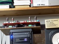
No progress on this project right now. The Simple P-P's have taken over, formed a union, and thrown all other amps off the workbench for now. There are 5 SPP boards either being experimented on, or being assembled into amplifiers in my lab right now. I have some minor issues to work through with the Simple P-P and a few amplifiers to finish but then there are two "flame throwing tube monsters" waiting. Believe it or not there is a verified 500 to 600 watts of tube power stacked in that small space on top of my computer.
The red PC board on the top is Pete Milletts "engineers amplifier". He posted the design here and on his web site. I looked at the design and it looked like something that I have tried before (with much smaller tubes), but never finished (yeah I have a MP degree too). It also looks like a simplified Tabor. I made the comment that it looked too big for the quoted 18 WPC, it should do at least 50 WPC. One thing led to another so I got one and proceeded to "turn it up till it explodes". Really! I blasted a capacitor clean in half (Sherri wasn't happy), there was a stain on the PC board where a resistor was, and a few more parts weren't feeling too good. After rebuilding and some serious hacking I succeeding in making the power meter read 240 watts on a single channel for about a minute, and had both channels running at the 200 WPC level for quite a while. I even hooked it to a CD player and my speakers. LOUD, real loud. Realizing that the probability of actually "shooting flames" at this level was pretty high, I swapped in some smaller tubes (way cheaper too) and dialed it in at the 100 WPC level. I listened to it for 3 days, and then set it on the shelf where it has been since.
The breadboard on the bottom is the one developed during this thread. We know that it can do 75 WPC in triode and nearly 100 WPC in pentode. I fully intend to complete at least one amp (probably 2) based on this breadboard. However I refuse to quit experimenting and learning new things (when you stop learning, your brain gets old, then.....), so there is another experiment to be tried on this breadboard.
There is a small group of audiophiles promoting DDR (Downward Dynamic Range). The theory goes that if you can't get the loud music any louder (we are already in the 200 watt range) you need to make the quiet parts quieter. Assuming adequate source material the limiting factor becomes hum, noise (hiss) and low level distortion. One of the "magic" solutions proposed by the "gurus" of this movement is a fully differential class A amplifier from the phono cartridge to the OPT. This driver circuit is already fully differential, and a fully differential class A output stage is is only a CCS away. The power would be in the 10 to 30 WPC range, but some of us have OPT's made for this! Got to try it.
Since blasting the red board into stratospheric power levels using "sweep tubes" I realized that these two technologies need to meet. So more experiments are planned here too.
I'm not really even sure what a sweep tube is
"Sweep tube" is the term used to describe a tube designed to "sweep" the electron beam across the face of a CRT in a tube type TV set. This term actually describes two different tube types.
The smaller type is the vertical sweep tube, also called a vertical output tube or a frame output tube. It's job is to move the beam of electrons that lights up the TV screen in an up and down motion, hence the term vertical sweep. This tube usually operates as a linear amplifier and needs to produce 3 to 10 watts of power at 50 or 60 Hz. The vertical output tube can be a triode or a pentode. In early TV sets common audio output tubes were often used, like the 6V6, 6W6, and even the 6SN7. Conversely, tubes designed specifically for vertical sweep usually make good audio output tubes.
The "big guy" is the horizontal output tube, or line output tube. Its job is to move the electron beam in a left or right direction. It however has another important job. It, with some help, is responsible for generating the high voltage that powers the CRT itself. The CRT in a large TV may require 25 KV at over 1 mA. This is 25 watts, add in the sweep power and the losses, and it is easy to see that this tube must produce 35 watts or more for several hours a day for years. Now you know why they are so big, BUT. The horizontal output tube doesn't operate in a linear manner, it works like a switched CCS. Pentodes make good CCS's, so a horizontal sweep tube will always be a big pentode, but not always a perfectly linear one. In TV use the tube is switched on forcing a constant current through the flyback transformer generating a ramp that is applied to the deflection yoke (a big electromagnet) for bending the electron beam. Once the beam reaches the edge of the TV screen the CCS is switched off quickly. The collapsing field in the flyback transformer is stepped up to a high voltage in a manner not unlike a cars ignition coil. In this case the HV is rectified and regulated for CRT use.
The horizontal sweep tube can see huge peak currents and some are rated as high as 1.4 AMPS! It also sees a lot of voltage. Most have DC plate voltage ratings from 550 volts to 990 volts, with peak ratings in the 2KV range. So if we find a sweep tube with good linearity we can make a big amplifier!
sorry to hear that George. my wife also went thru the same experience, but all tests failed to reveal any condition whatsoever....
That has proven to be the case. The biopsy was negative which is a very good thing, but some unexplained symptoms remain. With all of the ** she has been through lately it could all be stress related. I learned first hand what stress can do when I came to in the back of an ambulance (10 years ago) resulting in some major lifestyle changes. Sherri's grandmother (not her mother) passed away a week ago, so she is back up north for the third time this year. She also has to find a new house (all on one level) for her mother. I can see both of us moving her sometime in the near future.
If I'm understanding you correctly a stereo build would require two of your universal driver boards; right? For a power supply, I'm no where near being able to build my own so I'll probably have to rip off someone else's design. Any suggestions on where to start looking for something like that?
Yes two boards would be needed for stereo if they get built in their current configuration. I may decide to put both channels on a single PC board in the octal version. The power supply is highly dependent on the type of amp being built. I have been looking into a "universal" power supply, but obviously the requirements for a Tubelab SE and a "flame throwing tube monster" are a bit different. Assuming the use of this driver board and say 6L6GC's the power and regulation requirements vary from a class A triode amp to an a class AB2 pentode amp.
Well, I just got back from my last trip with work for a while, and start my 4 weeks of leave. I expect that I will start working on the amp after the weekend. Just before I found out I had to move house I was about to start this and while going over the schematic and doing some MJ reading, I think I found an error in the power supply with regard to the pass resistor calculation. The error was that I had not done any calculation, merely cut and pasted another design. The schematic is on another computer, so will post specific question regarding it tomorrow, maybe on the power supply forum...
Anyway, an issue I have to resolve before construction is tube choice. Yes, this will be a 6L6 amp, but I have a few quads of the coin based 6P6S-E Russian 6L6 type and two quads of 6BG6GAs. I was toying with the idea of having a switch to be able to swap between types. This would satisfy my desire to play with different tube types, but the reality is that it would add to the complexity of an amp that is already way more complex than anything I have attempted before, and I can see the potential for a fireworks display when i am putzing around swapping tubes and forget to throw the switch... I do have the converter bases for the 6BG6GAs, but there is a whole lot of wire crammed in to those bases joining up the required pins. This makes it difficult for any stopper resistors to be effective (if required) because there is 2-3" of wire between the tube base and the socket.
I am leaning towards just making it for the 6BG6GA and save on complexity etc.
Thoughts?
Anyway, an issue I have to resolve before construction is tube choice. Yes, this will be a 6L6 amp, but I have a few quads of the coin based 6P6S-E Russian 6L6 type and two quads of 6BG6GAs. I was toying with the idea of having a switch to be able to swap between types.
You won't need that switch. The 6L6, 807, 1625, 6BG6 are all the same type in different formats/pinouts. Pick the one you like best (or have the most replacements on hand). They will all sound the same, especially if you're including NFB.
I think he means that the switch would swap the pins needed to go from the 6L6 octal pinout to the 6BG6 octal+cap. I agree that the switch is error prone.
I personally would rather wire it for 6L6 and use the adapter. That said, if you don't plan on tube rolling and you have a cache of the "super" Philips/ECG 6BG6GA (really Sylvania 6L6GCs), then rewiring the socket for 6L6 and removing the plate caps down the road is not a huge effort.
I personally would rather wire it for 6L6 and use the adapter. That said, if you don't plan on tube rolling and you have a cache of the "super" Philips/ECG 6BG6GA (really Sylvania 6L6GCs), then rewiring the socket for 6L6 and removing the plate caps down the road is not a huge effort.
Sorry, yes, late at night when I typed. Meant the Russian 6P3S-E.
rknize, yes, yes and yes") ... I have two quads of the "super" Phillips tubes. I am thinking of going this route, but I am always looking for a use for those Russian tubes. They work OK in my Simple SE, but I always end up putting the JJ EL34s back.
... I have two quads of the "super" Phillips tubes. I am thinking of going this route, but I am always looking for a use for those Russian tubes. They work OK in my Simple SE, but I always end up putting the JJ EL34s back.
As an aside, my girlfriend is a professional classical musician (used to play in Opera Australia orchestra). I did some tube rolling in my Simple SE and asked her opinion. She had nothing invested in the process (she did not know which tubes were cheap, expensive etc) and thought that the JJ EL34s and the "super" Phillips 6BG6GA (with adaptor) sounded best, with the 6P3S coming second, JJ KT88 third.
Regards,
Chris
rknize, yes, yes and yes
... I have two quads of the "super" Phillips tubes. I am thinking of going this route, but I am always looking for a use for those Russian tubes. They work OK in my Simple SE, but I always end up putting the JJ EL34s back.As an aside, my girlfriend is a professional classical musician (used to play in Opera Australia orchestra). I did some tube rolling in my Simple SE and asked her opinion. She had nothing invested in the process (she did not know which tubes were cheap, expensive etc) and thought that the JJ EL34s and the "super" Phillips 6BG6GA (with adaptor) sounded best, with the 6P3S coming second, JJ KT88 third.
Regards,
Chris
Dang those "uninvested" listeners! Obviously you need to indoctrinate her further...
I've really enjoyed the Russian tubes, haven't heard the JJ's, but I REALLY love the idea of being able to get some decent tubes for great prices. It makes me a little sick inside to see some tubes going for more than the transformers in an amp (not the JJ's fall into this category).
I've really enjoyed the Russian tubes, haven't heard the JJ's, but I REALLY love the idea of being able to get some decent tubes for great prices. It makes me a little sick inside to see some tubes going for more than the transformers in an amp (not the JJ's fall into this category).
I REALLY love the idea of being able to get some decent tubes for great prices. It makes me a little sick inside to see some tubes going for more than the transformers in an amp (not the JJ's fall into this category).
I guess this is all relative. I consider the EH KT88 the best KT88's that I have but people in another thread use them for "test tubes". I look for cheap tubes that sound nice and make plenty of power. The 6GV5 that was on the dollar menu at ESRC was a good example. I also liked the 6HJ5, these crank out 100 WPC in the red board without breaking a sweat and really sound good. I will be getting 20 more of them tomorrow.
Anyway, an issue I have to resolve before construction is tube choice....I am leaning towards just making it for the 6BG6GA and save on complexity etc. Thoughts?
Well, just my opinion, but if it was mine I would wire it for a 6L6GC, and add a jumper from pin 1 to pin 8. This opens up a long list of possible tubes including the usual 6L6 types, the EL34's, KT88's and some you don't think about like the 6BQ6's and the 6DQ6's. Use the adapters for the 6BG6's. The adjustable bias allows the use of all of these, and the 6BQ6's are a real sleeper often available for $1. You will need a plate cap. I use a pin jack or a banana jack on the top plate. Plug the wire in when you need it.
Thanks for the input.
Is there any issue with the wiring inside the adaptor for the 6BG6GA? The adaptor is a tube base/socket combo with short wires changing the effective pinout. If I remember, I think that the wires were about 3" long. I am thinking oscillation, grid stopper effectiveness etc. If there is no perceived problem, I will take this advice and wire for 6L6 (and jumper as advised) and use adaptors.
It has been a little while since I had my mind on these things, so I am trying to get back up to speed. I tend to build the power supply first, then test it, then heaters, then signal wiring - testing as I go. I was reading the section in Morgan Jones on regulator design for a 300V power supply, p 360-362. Specifically, on page 362, he mentions the 3K resistor in his circuit (R32 - 40.2K in my circuit) that is in series with the 15V zener, and should be specd to pass > 5mA. My calculations for 7.5mA through the zener (D3) are:
DC voltage from the rectifier = (400v x 1.414) - rectifier drop = about 550v
regulated voltage is 400, plus 15v for the zener =415v.
Voltage drop will be 550-415=135v, 7.5mA gives 18K resistor and 1.025W
So, I should replace R32 (40.2K) with 18K and use a 3W resistor?
MJ's design does not incorporate zeners D1, D2 or D4 in my circuit, not sure if this makes any difference to calculations...
Could someone with some knowledge of these regulators please check to see if I am on track?
Regards,
Chris
Lets think about why he might suggest more than 5mA. The BJT he is using needs to be supplied with base current. Also, the zener might have a lower dynamic impedance at a higher current. Do we need it to be extra low here? Look at the diode curves and make a judgment call.
In practice, I use between 1 and 2mA here with mosfets and things seem to work well. Would more be better?
By the way, your method seems sound on calculating the current through the resistor.
The extra diodes should act like open circuits in normal operation. They are there to protect against stuff that happens when you power up/down.
How about R33? What made you choose 11 Ohms?
It looks like you have about 10mA drawn from the heater reference and voltage set dividers. This is good, it should guarantee regulation even with no external load on the regulator. Some like to design them to draw less (more efficient, cheaper resistors). I like the fact that it is easier to troubleshoot and test when it always puts out the right voltage.
Thanks Spreadspectrum, I suspect you are right about R17 and R56. I will check.
As for the full 400V for first stage, I suspect that tubelab first drew it as you describe, I will go back and check...
As for the 11R, I am not exactly sure, there are so many posts on this thread, it is hard to remember. I suspect that my regulator is a straight copy of a schematic you were kind enough to supply. If anything, I think (?) I may have only changed the value of the voltage divider resistors to suit the output voltage.
As for the >5mA through the zener, MJ just states that it is for reduced noise.
Thanks for your continued help!
Chris
I'm a bit surprised to see the plates powered by the Miata regulator. That is a lot of current for it to pass and any power supply noise there is common-mode. Maybe I missed something earlier in the thread, but I'd think you'd just want to feed the plates of the input and LTP sections from the regulator?
It may make a difference for noise. The supplies that I built look like a flat line on the most sensitive setting of my scope, and I don't have a better way to measure noise so I wouldn't know if it makes much difference in practice.
The mosfet in the regulator is configured as a follower, so as current increases, the 11 Ohm resistor will start dropping voltage when more current is drawn through the regulator. I think that the purpose is to make the regulator short-circuit tolerant. The resistor will eventually starve the LM317 for voltage. You could leave out the resistor altogether, but you will not have any protection. You probably need to figure out how much current you will need total and make sure that you have enough voltage across the LM317 for it to work well at the maximum current you expect to see. The data sheet is your friend. Change the resistance value if you need to.
rkinze is right. You will probably need a nice heatsink for this thing. There are some other things you can do to reduce dissipation. The best thing you can do is drop some voltage other ways. Since you are using a tube rectifier, you can put in extra series resistance between rectifier and capacitor. The rectifier will like this and it will last longer, and it will eat up a bit of voltage.
I have used Maida regulators on PP output stages and I like having the stiff supply on an AB output stage. Bass seems to hit a little harder. However, it would still sound pretty good with a simple plate supply.
I built my amp originally with a CLC filter power supply. One thing I hated was that due to the high DCR of the choke, you have to adjust bias like three times on triode-connected output tubes. By the time you get to the last tube, the first tube is way off due to the sagging supply voltage. The more current gets drawn, the lower the supply would go. The Maida's voltage stays right on no matter what the load. Bias once and you are good. Also, you are regulating the bias supply, so you have to regulate the B+ or bias will vary wildly with line voltage fluctuations.
- Status
- This old topic is closed. If you want to reopen this topic, contact a moderator using the "Report Post" button.
- Home
- Amplifiers
- Tubes / Valves
- 6L6GC AB2 Amp