Ok, did the clamping:
COM to LO to VCC, and VS to HO to VB.
Did it with 4 x 1N4148 as this was what I had.
No improvement what so ever
VS is already clamped to COM through lower bodydiode and external ES1D in parallel.
Don't know what is wrong
IN4148 is too much fragile for handling peak currents atleast use BAV21 or a bigger UF4007.........If you have access to SMD packages then go for it.
IN4148 is too much fragile for handling peak currents atleast use BAV21 or a bigger UF4007.........If you have access to SMD packages then go for it.
Hi Workhorse
Yes I know. My thinking was; they are fast, and they might last for a few trials, and it any of them burn, I'll know there is a large current flowing, hense showing that this could indeed be the source of the problems.
Nothing bad has happened .... therefor this is NOT the source of my current problems.
In future designs, these clamping diodes will be in though ... using fast tough SMD types
After further work, I can't help to think it has something to do with the use of LT1711. My daughter board with either MAX913 or MXL1016 works without problems. The current drawn by the LT1711 also seems quite excessive ... being 30 mA DC and AC peaks of same magnitude. This also stresses the small regulators made by single FZT657/FZT757, which becomes very hot.
I'm driving the LT1711 +-5V at both input stage and output. This should be possible according to the data sheet, but I'm begining to thik that this is maybe not a good idea after all (and not really necessary either).
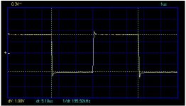
But I like the look of the output of the 1711 ... it's just so square and clean ...
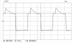
Looking at the output of either MAX913 or MXL1016 it looks nice on the unloaded output, but loaded by the levelshifter circuit it looks a bit strange (see picture below .... second picture is the output of the LT1711).
Attachments
After further work, I can't help to think it has something to do with the use of LT1711. My daughter board with either MAX913 or MXL1016 works without problems. The current drawn by the LT1711 also seems quite excessive ... being 30 mA DC and AC peaks of same magnitude. This also stresses the small regulators made by single FZT657/FZT757, which becomes very hot.
After going thru several datasheets of high speed differential/complementary output comparators such as[LT1016, LM360] they seems to be current hungary, nothing to surprise
Try to use SOT-223 package for regulators with good copper plane for sinking heat
Yes of course, the faster, they are the more current hungry ..... but +-30mA + 30mA spikes is quite a lot.
FZT657/FZT757 are in fact SOT-223 .... but I could give them a bit more copper though
See post #125 for the level shifter:
http://www.diyaudio.com/forums/class-d/154244-6000w-irs2092-3.html#post2042052
It works ok, but could be faster .....
..... but +-30mA + 30mA spikes is quite a lot.FZT657/FZT757 are in fact SOT-223 .... but I could give them a bit more copper though
See post #125 for the level shifter:
http://www.diyaudio.com/forums/class-d/154244-6000w-irs2092-3.html#post2042052
It works ok, but could be faster .....
Yes of course, the faster, they are the more current hungry
FZT657/FZT757 are in fact SOT-223 .... but I could give them a bit more copper though
See post #125 for the level shifter:
http://www.diyaudio.com/forums/class-d/154244-6000w-irs2092-3.html#post2042052
It works ok, but could be faster .....
Try connecting in Common Base fashion , you are using common emitter type which is plagued with storage time effects.
Hi Workhorse
Sounds right that a common base type would be faster, but I'm not quite sure how that would look .... could you draw that up?
Thanks in advance, Baldin
Omit Q1 & R2 and join R3 directly to output of comparator. If possible then decrease value of R3 to 560ohm and R5 to 680ohm.
BTW why are you using logic gates when your comparator is already giving you 2 out of phase outputs, simply level shift the both complementary outputs of comparator and add Deadtime and feed directly to gate driver chip.
Last edited:
Hmmm, Workhores that just works so much faster (in sim so far ) .... thanks a lot
Well the logic is there mostly due to history ... started out using a comparator with only one output ... I'll loos it in next round, just going for two level shifters and two following RCD circuits ... less components and more compact design ...
Best regards Baldin
) .... thanks a lot Well the logic is there mostly due to history ... started out using a comparator with only one output ... I'll loos it in next round, just going for two level shifters and two following RCD circuits ... less components and more compact design ...
Best regards Baldin
Ok, tried it out in real life ... just kept R3=2k2 and R5=2k7 for startes.
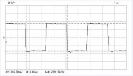
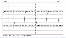
Both MAX913 output and Level Shifter output looks much better.
Speed is faster also, caused the switching freq to shift from 270 kHz to around 290 kHz.
Will sim a little to find lower values for R3 and R5, which will not burn, to get even better and faster shifting
Both MAX913 output and Level Shifter output looks much better.
Speed is faster also, caused the switching freq to shift from 270 kHz to around 290 kHz.
Will sim a little to find lower values for R3 and R5, which will not burn, to get even better and faster shifting
Attachments
Last edited:
Ok, tried it out in real life ... just kept R3=2k2 and R5=2k7 for startes.
Both MAX913 output and Level Shifter output looks much better.
Speed is faster also, caused the switching freq to shift from 270 kHz to around 290 kHz.
Will sim a little to find lower values for R3 and R5, which will not burn, to get even better and faster shifting
Resistor value should be reduced and also use sanyo pnp high speed video transistor TO-126 pack for helping in dissipation or get it in D-PAK.
i have seen this " http://datasheet4u.com/download.php?id=595690 " and the reansistors are 330W, so if we use 12 transistor (btl) we have max 3960w....
discrete driver
Driving Large-Die and Paralleled Power MOSFETs Is Easy with the Right Techniques
In this paper, mosfet totem pole (inverting) seems better than bipolar totem pole (non-inverting).
But why this mosfet totem pole is less popular than bipolar one?
Driving Large-Die and Paralleled Power MOSFETs Is Easy with the Right Techniques
In this paper, mosfet totem pole (inverting) seems better than bipolar totem pole (non-inverting).
But why this mosfet totem pole is less popular than bipolar one?
i have seen this " http://datasheet4u.com/download.php?id=595690 " and the reansistors are 330W, so if we use 12 transistor (btl) we have max 3960w....
Wow, I always thought that the power had to be dissipated in the load, not in the amplifier
Driving Large-Die and Paralleled Power MOSFETs Is Easy with the Right Techniques
In this paper, mosfet totem pole (inverting) seems better than bipolar totem pole (non-inverting).
But why this mosfet totem pole is less popular than bipolar one?
Quote from that paper:
"Unlike the bipolar design, the MOSFET totem pole is inverting and offers voltage gain to improve on the pre-driver rise and fall times. This driver suffers from shoot-through current caused by the threshold voltage overlap during on and off transitions resulting in increased drive power requirements. Because of the inverting nature of the driver, it may cause false turn-on of the power device during power up and power down, requiring under voltage detection and hold-off circuitry."
More reasons:
-Every high and low side gate driver IC is non inverting
-Almost every gate driver IC puts its outputs in a low state during shutdown
-With bipolars you can get close to 10A peak from a SOT-23
in my circuit is around 20V/ns for turn off and around 15V/ns after reverse recovery.
Of course, for high end I would probably be using pulse transformers to produce isolated high side supplies, and one regulator for each gate driver, but in this amplifier there is no room for that. I would probably be using separate optocouplers or transistors for level shifting too, for minimum skew and delay, but optos can't whitstand as high dv/dt as IR drivers (10-15V/ns vs 50V/ns).
Hi Eva,
I have to thank you for this discussion. It helped to find a design flaw in theory, before getting headache with the real thing.
Today
was the first day I found time again for my hobby after my move Remembering our discussion, I started to analyse the switching conditions in my circuit more detailed and I am coming to the conclusion that also my di/dt limiter cannot avoid fast dv/dt under all conditions.
I found load situations which exceed the the allowed dv/dt of HCPL9030 (15kV/us) isolators and especially during heavy load conditions it is not really convincing to rely on components that are hopefully better than their spec...
I am considering to use IR half bridge drivers and pay the price of reduced timing precision.
In fact the IRS20124S is looking not so bad. Low propagation delay and a clever overcurrent protection. In combination with simple bipolar buffers it might serve my design needs.
Anybody out there who has already real life experience with the IRS20124S?
I have seen full-range class D amplifier modules that use them, with bipolar buffers and IRFB4227. I'm not allowed to tell more, but they will work for sure
I'm considering IRS2011 and IRS20124 for my next projects. IR2110 is very reliable and produces consistent timing, but with bipolar buffers the lower output impedance is not really required, the propagation delay is high and the package is a bit bulky too.
I'm considering IRS2011 and IRS20124 for my next projects. IR2110 is very reliable and produces consistent timing, but with bipolar buffers the lower output impedance is not really required, the propagation delay is high and the package is a bit bulky too.
Last edited:
Hi Choco and Eva
My thoughts exctly. I'm going for IRS20124 next.
IR2110 works great, but IRS20124 will give both dead time delay adjustment and current protection for free. Worth considering I think
I was actually hoping to skip the buffers, though it is only 4 small transistors. How bad would it be to drive e.g. IRFB4227 at say +- 60V?? ..... You have probably already made such calculations
Using buffers would maybe also allow for smaller gate resistors ... or skipping them all together for higher switching speeds
Why not use IRS20957S .... that would also save the levelshifting at the input ... but I guess you can do that much faster with a good high speed transistor (as Workhorse suggested) ......
Last edited:
- Status
- This old topic is closed. If you want to reopen this topic, contact a moderator using the "Report Post" button.
- Home
- Amplifiers
- Class D
- 6000W By IRS2092