I spotted something amiss at the SG4 output connector. I can't be sure if the wiring is correct from the picture. I seem to see you could have plugged in wrongly.
The bottom row pin at the output is all common ground. The upper pins are the individual phase output. The picture show one connector plugged to 2 ground pins and the other 0 & 90 degree pins. Check again.
The bottom row pin at the output is all common ground. The upper pins are the individual phase output. The picture show one connector plugged to 2 ground pins and the other 0 & 90 degree pins. Check again.
Attachments
I probably should have used different wire colours so it could be less confusing. Here's what I've done regarding the SG4 output:
The ground output for 0&90 (black and white wires) are joined together into the red wire going into the ground input of the gain board.
0 phase (gray wire) and 90 (black wire) are individually connected to their inputs on the gain board.
The ground output for 0&90 (black and white wires) are joined together into the red wire going into the ground input of the gain board.
0 phase (gray wire) and 90 (black wire) are individually connected to their inputs on the gain board.
I found something strange.
While on 33 RPM and with stable speed, I cant toggle the switch to 45 RPM and the platter will spin at 45 RPM (with a lot of vibration). But if I remove the belt from the pulley, set the SG4 to 33, turn it on and then change it to 45 RPM, the motor will stop.
The motor will also stop if I remove the belt with a pencil while it´s on and at 45 RPM.
It only works with the belt on as if the platter´s inertia is acting directly into making the motor spin at 81 Hz.
Last edited:
Is this with a Hurst motor? I have 5-6 of their motors and some will run with dual phase at 45 RPM and some will not. It seems to be related to the bearing vibration; some of the motors have a brass collar to control this. I contacted Hurst in an attempt to find an answer to this, but they did not have any insight.
It might be better in your case to run single phase and switch the phase cap between 33 and 45 RPM.
It might be better in your case to run single phase and switch the phase cap between 33 and 45 RPM.
Powering the SG4
I am building a SG4 with D class amp and 60W 24V switching power supply. in short, this set up.
I do have a question.
Can I safely power the SG4 module from this 24V power supply? It has build in 78xx regulaters, 8V and 5V that are rated at 35V max input.
Or do I get a small dedicated supply? Or, another option, do I put an extra voltage regulater between 24V to the SG4, to get it down to 12V?
Thank you!
Marc
I received the TDA7492 Class D amp from e-Bay yesterday:
TDA-7492 50WPC Class D Amp
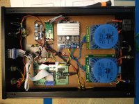
The PCB is 3" x 2.5", about the same size as the SG4. I connected the outputs to an Amgis L01-6362 12V toroid transformer and powered the amp using a GST60A24 24VDC 60W wall adapter. To drive the toroid output to 120VAC no load, you will need to reduce the output of the SG4 to 920mVPP using a pot or a fixed voltage divider of 8.2K and 1.8K resistors.
Below are the schematics for single phase 115 and 230VAC outputs as well as a picture of the supply powering a 19W Lenco motor. The TDA-7492 PCB comes with its own heat sink, and because it is Class D, requires no additional heatsinking (the temp topped out at ~100°F after 1 hour.
The amp was $10, the wall adapter to power it was $18 and the toroid is $25.
Be sure to observe the polarity markings on the transformer and the TDA-7492 outputs.
I am building a SG4 with D class amp and 60W 24V switching power supply. in short, this set up.
I do have a question.
Can I safely power the SG4 module from this 24V power supply? It has build in 78xx regulaters, 8V and 5V that are rated at 35V max input.
Or do I get a small dedicated supply? Or, another option, do I put an extra voltage regulater between 24V to the SG4, to get it down to 12V?
Thank you!
Marc
I'm very enthused with connecting 2 phase later on to my Hurst 230V/50hz motor model. I hope I don't face silly issues. I never knew such motor issues. I had simply thought as long as the correct connections, it should work flawlessly and reliably unless it way out of specs.
Zeno, just apply 10 to 12VDC and its safest bet to work properly without any undue stress.
Zeno, just apply 10 to 12VDC and its safest bet to work properly without any undue stress.
Last edited:
I'm very enthused with connecting 2 phase later on to my Hurst 230V/50hz motor model. I hope I don't face silly issues. I never knew such motor issues. I had simply thought as long as the correct connections, it should work flawlessly and reliably unless it way out of specs.
33 RPM doesn't seem to be a problem, as the motor is designed to work 50/60Hz; it only happens at the higher frequency.
If you really want to upgrade, go with the 3 phase BLDC motor; no vibration, no speed issues, low voltage, higher torque and lower noise.
If you power the SG4 from 24VDC, the 5V reg will need a decent heat sink (also ensure the LM78L08 is rated to 26VDC or higher). It might be easier and better to put a 12V reg between the 24V supply and the SG4 (also with heat sink).
As I suspected! Some small electrolytic caps on in and out?
Marc
As I suspected! Some small electrolytic caps on in and out?
Marc
If the reg is far from either the source or the load, then yes should add .1uFd caps on either or both for stability.
If the reg is far from either the source or the load, then yes should add .1uFd caps on either or both for stability.
Perfect!
Bill,
It is a Hurst indeed, PA direct drive 300 RPM.
I´ll keep it running on dual phase for now, only in 33 RPM as I´m waiting for a new solder station to arrive... I´ll remake the connections in single phase and test it.
I should then reinstall the original VPI sama board (with 2 caps) right?
It is a Hurst indeed, PA direct drive 300 RPM.
I´ll keep it running on dual phase for now, only in 33 RPM as I´m waiting for a new solder station to arrive... I´ll remake the connections in single phase and test it.
I should then reinstall the original VPI sama board (with 2 caps) right?
I should then reinstall the original VPI sama board (with 2 caps) right?
You will need a phase cap for single output drive, yes. The cap will be optimum values for each frequency, so you might consider a switch on the SAMA to switch in (or parallel) different caps for the 2 speeds to give the best performance.
Well this is a bit confusing to me.
Let me ask you something: The Eagle PSU was a single or dual phase controller? Based on what I´ve read online, I believe it was single phase. The reason why I´m confused is that I thought the SG4 on single phase would be very similiar to the Eagle (and also the SDS) and it was a kind of plug-n-play operation, without the need to make any modifications in the phase cap inside the motor... or am I wrong?
If I need to get a different cap for each frequency, than would this make the possibility to have minor frequency adjustments not possible as each increasing/decreasing in its value would make the cap installed to be not optimized?
The original VPI motor board has a .47uf 600VDC between the Red and Black wires, and a 102 ceramic cap after the switch.
Well this is a bit confusing to me.
Let me ask you something: The Eagle PSU was a single or dual phase controller? Based on what I´ve read online, I believe it was single phase. The reason why I´m confused is that I thought the SG4 on single phase would be very similiar to the Eagle (and also the SDS) and it was a kind of plug-n-play operation, without the need to make any modifications in the phase cap inside the motor... or am I wrong?
The Eagle (and SDS) were single phase. The motor will work at both speeds with only one cap, but it will not be optimum at 45 RPM
If I need to get a different cap for each frequency, than would this make the possibility to have minor frequency adjustments not possible as each increasing/decreasing in its value would make the cap installed to be not optimized?
Changing the cap for each speed will get you closer to the optimum at both speeds. Small incremental frequency changes will not change the phase relationship significantly (you are only changing 1-2Hz max). There will be a significant change between 50 and 67.5Hz.
The original VPI motor board has a .47uf 600VDC between the Red and Black wires, and a 102 ceramic cap after the switch.
The 0.47uFd cap is the phase cap. The 1000pfd cap across the switch is an arc suppressor.
Thanks for the enlightenment Bill.
I think implementing this cap switching system on the VPI SAMA is a bit of a challenge for me and not worthy since I plan to move on with the BLDC motor later on.
I´ll keep the SG4 on dual phase and run it exclusively at 33 RPM, changing the belt on the pulley when 45 RPM is needed (not even 5% of my records are 45 RPM anyway).
I´ll start making the arrangements to build the MA3D board and upgrade the motor to the 24v 3 phase BLDC... I think you´ve mentioned somewhere that one of them is a fit into the VPI SAMA and would be just a matter of finding a good pulley. I´ll dig into the BLDC thread.
I have one comment and two questions.
Comment: be informed that some of arc suppression caps (typically installed parallel to switch, or I tried RC (100R + 0.1uF)) can have a little current go thorough (small current leak) and when your switch is off, your motor will get small current and it will vibrate with no rotation (it is quite audible too).
http://www.littelfuse.com/~/media/e...load_arc_suppression_application_note.pdf.pdf
I ended up same with the setup as in Figure 4.
Questions: I tested TDA7293 for SQ, gain modification and heat sinking action. All these aspects are fine. However, I hear some level of 120Hz buzz/hum. The amps are not in enclosure and I’m probably picking up some EMI/RF. Anyway, to GND it on CT on secondary does not change humming. 10R GND elevation either did not change it. I changed Filter caps from original 2200uF to 3300uF and no change. Does low probably rectifier swithing related hum can be an issue for our needs for 60 and 81Hz transformation?
What is a general GND strategy for our motor control unit?
Last edited:
Every situation can be different and trial and substitution seem to be useful for troubleshooting. Certain cartridges are also more susceptible to hum than others.
If the hum is caused by EM radiation into the wires or cartridge, then moving the high power stages of the supply as far away as possible and/or shielding the supply can help. If the hum is conducted, it may be that the table was using the motor earth ground which is now isolated through the supply. Connecting the SG4 and/or amplifier ground plane to earth ground may help. Grounding the table, tonearm, platter or motor assembly to the stereo ground may also help.
If the hum is caused by EM radiation into the wires or cartridge, then moving the high power stages of the supply as far away as possible and/or shielding the supply can help. If the hum is conducted, it may be that the table was using the motor earth ground which is now isolated through the supply. Connecting the SG4 and/or amplifier ground plane to earth ground may help. Grounding the table, tonearm, platter or motor assembly to the stereo ground may also help.
Hi Bill,
My apology since probably I confused you by saying SQ test for that amp. I will use it (TDA7293) on table motor driver for single phase out with your SG4.
No cartridge, actual TT or any other source involved in my test. I shorted inputs and connected it to 26.4VAC toroid. 8R speaker (do not have lower impedance one) connected to the out.
The rest of GND info is a typical approach and it is clear.
Thank you for that. Alex
Many time I told to myself not to read and answered during work hours. Here it is again....") . I got your point Bill and all what you mentioned is make sense. Moved toroid bit further and hum is decreased significantly. It is EM that my amp picked up. I’ll try to use Mu metal foil in my enclosure to attenuate it. Not much room there to distant enough all components. Thank you.
. I got your point Bill and all what you mentioned is make sense. Moved toroid bit further and hum is decreased significantly. It is EM that my amp picked up. I’ll try to use Mu metal foil in my enclosure to attenuate it. Not much room there to distant enough all components. Thank you.
. I got your point Bill and all what you mentioned is make sense. Moved toroid bit further and hum is decreased significantly. It is EM that my amp picked up. I’ll try to use Mu metal foil in my enclosure to attenuate it. Not much room there to distant enough all components. Thank you.- Home
- Source & Line
- Analogue Source
- 60 WPC Amplifier for DIY Turntable Motor Drive