Thanks, Bill!!! that makes perfect sense AND helps me determine how to connect the 3 phases when I get the new controller finished.With the phase cap, the motor is running as 3 phase, but not optimally. The 2 direct connections can be looked at as running 0° and 180° since they are out of phase with each other. The lead connected to the cap is ~+90° referenced to the 0° input. So instead of running 0/120/240, it is running 0/90/180. This works, but with higher vibration.
Hi,
Can anyone tell me the gain of the MK-154 amplifier with the 2.2k resistors installed as detailed in post #1? I'm assuming the MK-154 inputs are AC coupled, is that true?
Also, is the winding ratio of the LP12-1900 transformer with parallel connected primaries and secondaries considered to be around 115/6.3 = 18.25 turns/turn? Anybody know the true winding ratio of a 115V/6.3V transformer?
I'm setting mine up to drive a 3 phase papst motor and want to ensure I calculate the referred winding resistance and appropriate ballast resistors to prevent my amps from going into overcurrent protection.
Best regards
The gain is the ratio of the feedback resistor connected between pin 3 (output) of the LM3886 and the inverting input (pin 9) and the resistor from pin 9 through a cap to ground, plus one. On most versions of the MK-154, the unmodified values are 22K and 680Ω so the gain is ~33.35. With 2k2 and 680Ω, the gain is ~4.23x. Some of the LM3886 boards out there may be different, so it is best to measure the gain or put a pot between the SG4 and the amp to adjust the level.
The turns ratio of the transformer will be the UNLOADED output voltage divided by the input voltage. For the LP12-1900, the unloaded output is ~8VRMS with 115VRMS input so the turns ratio is closer to 14.375. Powering the secondary with 8VRMS should produce ~115VAC at the primary, but that voltage will drop when loaded.
The SG4 ramps up the voltage at start up, so ballast resistors should not be necessary to prevent over current at start up.
According to the data sheet the TDA-7492 can be powered from 12VDC, but the power out capability will be only 25% of that at 24V (-6dB or 12.5WPC vs 50WPC). You would also need an output transformer with a 6V secondary which lowers the impedance seen by the amp by a factor of 4 (vs a 12V xfmr). The chip shuts down at ~3A (over current protection) which will occur sooner with a 6V xfmr. In the case of the 19W Lenco motor, the motors impedance=115^2/19=696 Ω. The 12V xfmr has a turns ratio ~8:1 so the impedance seen by the amp is 10.9 Ω. With a 6V xfmr, the impedance seen by the amp will be ~2.7 Ω.
The 24V wall adapter is only $18. It's small, has over current protection and the output is well regulated with no PS ripple. Hard to beat that.
Power bricks for old laptops are a cheap (or even free) source of SMPS, but 24V was not a common voltage. I have one from an old laptop rated 19V@4.5A. I would like to use it for this project. Would it be reasonable to power the TDA7492 with 19VDC, and use a pair of 9V output transformers? (2 phase).
Also, my Thorens motor is rated 15W, though I suspect that is generous. Driving each coil from its own transformer in 2 phase mode, would 10VA be too small? I see Antek have some 10VA toroids which are very compact and reasonable inexpensive. The 25V equivalent is only a little bigger and only a dollar more, but I like the idea of keeping things compact.
Thanks Pyramid, I'll get the 25 VA xformers. (I recall the late AndrewT always said to derate transformers by at least 50% to keep them running cool. There is no point pushing this when the next bigger ones are only an extra dollar and maybe half an inch extra diameter.)
Glad to hear the 19V supply with 9V transformers should work.
I now have SG4 and encoder circuit boards, SG4 chip (thanks Ralph!), a bag of encoders (why do they ship without a nut?), and the TDA7492 amp module. Time to order a case and parts and get cracking!
Glad to hear the 19V supply with 9V transformers should work.
I now have SG4 and encoder circuit boards, SG4 chip (thanks Ralph!), a bag of encoders (why do they ship without a nut?), and the TDA7492 amp module. Time to order a case and parts and get cracking!
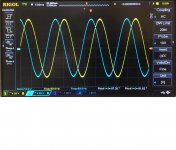
I have some high pitch hiss-noise that is coming from my unit. Can’t tell for sure, but I assume it is coming from output transformers. It is a bit overkill for my current motor in-use… I use two Talema 25VA 12 to 115V (70062K) to run 3W Hurst 3001-001 (A, AB Direct Drive Permanent Magnet AC Synchronous Motors). It seems all connected correctly and even during standby, it is a bit sounding that hiss. Both (0 and 90 Deg) sinuses are looks fine and understored. No visible noise either. Is anyone experienced with the same issue? It is not that it is bugging me too much, and I’m sure it will be almost not audible when I’ll close top lid of my enclosure, but any way do not like some unexpected phenomenon. DC? GND loop? Core saturation? Please share with your experience.
With the SG4 at standby, there should be no AC output (the outputs will idle at 2.5VDC so make sure the input to the amp is AC coupled). If you are reading an AC voltage on either the SG4 output or the amp output, something may be oscillating. Easier to trouble shoot if you have a scope.
What are you using to power the amplifier? Could the noise be coming from there?
What are you using to power the amplifier? Could the noise be coming from there?
With the SG4 at standby, there should be no AC output (the outputs will idle at 2.5VDC so make sure the input to the amp is AC coupled). If you are reading an AC voltage on either the SG4 output or the amp output, something may be oscillating. Easier to trouble shoot if you have a scope.
What are you using to power the amplifier? Could the noise be coming from there?
Let me check with my scope and DVM tonight and update you. I use advised LP-40-600 transformer for TDA7293 amp. Will see its datasheet for signal coupling. Thank you a lot for direction.
Thank you for troubleshooting tips.
I don’t see any abnormality during troubleshooting and mentioned by Pyramid setup is seems as it should be.
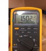
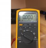
a. Amp is AC coupled and no DC is going through it. I see 1.5 VDC during STBY on input and “0” VCD on output.
b. AC going through the AMP and DC component of it is “0”.
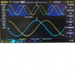
c. Output signal looks clean
d. No GND loop.
I attached images with correspondent titles that might give you some info.
Hiss is still there and my last resort is to check output transformers connections for 12V parallel setup. Maybe I messed up right there…, but I checked that prior install.
Maybe I need to go back and recheck that.
Any other ideas?
I don’t see any abnormality during troubleshooting and mentioned by Pyramid setup is seems as it should be.
a. Amp is AC coupled and no DC is going through it. I see 1.5 VDC during STBY on input and “0” VCD on output.
b. AC going through the AMP and DC component of it is “0”.
c. Output signal looks clean
d. No GND loop.
I attached images with correspondent titles that might give you some info.
Hiss is still there and my last resort is to check output transformers connections for 12V parallel setup. Maybe I messed up right there…, but I checked that prior install.
Maybe I need to go back and recheck that.
Any other ideas?
Attachments
What are you using to power the amplifier? Could the noise be coming from there?
If trust my subjective ears, the noise is coming from 2 output transformers. Not from amps or correspondent feeding transformer. The pitch of noise is changing when I touch output transformers plastic enclosures.
I fond out that my hiss is coming from 2 (simi-toroids) transformers. Pyramid, as always, was right. One is Stancor LB type 12v and set to feed SG4 via LM317 and second is Signal LP-40-600 24VA with 20-0-20 for for my amps. It is not loud and barely noticeable when my lid is closed. I can live with it, but please let me know if you have some knowledge about such hiss attenuations. My mains might contain some small DC and I’ll try to use DC blocker. What else to try?
Last edited:
You could do that, but as rif stated, the 12V drop at 80mA will dissipate ~1W. You will need to heatsink the 7812.
You do not need a delay circuit. The GST60A24 is well regulated and will not drop out unless it is overloaded.
I tapped mine going to a 7812 and It overloads. After about 30 minutes I get Charlie brown noises and no power. might have to add another power source and see what happens.
Last edited:
I have built an SG4 driving TDA7294 amps to power a Papst 3 phase motor. The transformers get almost too hot to touch after about 30 minutes of use. Is this normal?
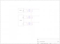
I have the 0 and 120 degree output feeding to one TDA7294 amp. Each channel is connected to a separate transformer. The 240 degree signal goes to one channel of the second amp, and drives a 3rd transformer. The primaries are connected in series and so are the secondaries. I originally connected the primaries in parallel and the secondaries in parallel but this didn't seem to work.
As mentioned, the transformers get almost too hot to touch (5 seconds maximum touch) after about 30 minutes. After running for a couple hours, the motor slows down substantially.
I'm assuming that I have something amiss and would appreciate suggestions. thank you.
A wiring diagram would help.
So would a list of transformers (single/dual primary/secondary, primary/secondary voltage and VA ratings). What about DC supply voltage to the amps?
Instead of primary and secondary windings, how about low voltage and high voltage?
Ooops, sorry.
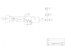
Attached is a crude diagram (the PDF file). It's based on the project done by ralphfcooke and his schematic is also attached for reference.
The transformers are Triad VPT24-1040. Primary is 115/230 and secondary is 12/24 rated at 25VA. These three transformers are together in a stack (don't know if that causes any problems).
I'm using a voltage divider to drop voltage from the SG4 to 287mV (rms)
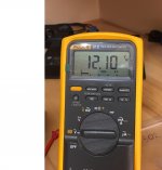
The output from the TDA7294 amp is 13.68VAC (rms) connected to the transformer but not the motor.
The output from the transformers is 118VAC (rms) not connected to the motor.
A single Meanwell switching power supply provide power to both amps and the SG4 (through a DC buck converter) The power supply is rated 20V 8A 160W
Thank you for your assistance..
Attachments
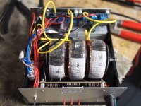
The transformers are Triad VPT24-1040. Primary is 115/230 and secondary is 12/24 rated at 25VA. These three transformers are together in a stack (don't know if that causes any problems).
Using the 24V supply and the TDA7492 in BTL mode, the low voltage secondary of each xfmr should be in parallel (make sure to observe the correct polarity of each winding).
The high voltage primary windings of each xfmr should also be connected in parallel, dot to dot and non-dot to non-dot.
The low voltage secondaries should not have any connection between xfmr 1, xfmr 2, or xfmr 3. Check the outputs at the high voltage primary with no motor connected and without any connection between high voltage primaries of xfmr 1, xfmr 2, and xfmr 3.
If you have ~115VRMS at each xfmr output, connect them together in a "star" configuration by connecting all three (6 in parallel) non-dot wires together; insulate this connection as it does not connect to the motors.
The other three (6 in parallel) dot wires should go to the motor, one for each phase.
Attachments
Using the 24V supply and the TDA7492 in BTL mode, the low voltage secondary of each xfmr should be in parallel (make sure to observe the correct polarity of each winding).
The high voltage primary windings of each xfmr should also be connected in parallel, dot to dot and non-dot to non-dot.
The low voltage secondaries should not have any connection between xfmr 1, xfmr 2, or xfmr 3. Check the outputs at the high voltage primary with no motor connected and without any connection between high voltage primaries of xfmr 1, xfmr 2, and xfmr 3.
If you have ~115VRMS at each xfmr output, connect them together in a "star" configuration by connecting all three (6 in parallel) non-dot wires together; insulate this connection as it does not connect to the motors.
The other three (6 in parallel) dot wires should go to the motor, one for each phase.
Thanks, Bill. I wondered if that was the problem. If you have time, could you please explain why the connection in parallel vs. series makes this difference? Learning is one of the most fun parts of this hobby.
Thank you.
- Home
- Source & Line
- Analogue Source
- 60 WPC Amplifier for DIY Turntable Motor Drive