Of course they'reThe MOSFET's and resistor burn 5 to 8 watts -- are they properly heat-sinked?
For anyone else who used the Landfall chassis system -- I have a bunch of Pomona Triple Banana Jacks which I've used for a variety of test equipment projects. The spacing for the Pomona's are a good fit with the Landfall. Nevertheless you will need two fiber or nylon washers if you use the Pomona's -- a 0.500" OD/0.2500" ID for inside the hole, and a 0.750" OD/0.250" ID to secure the jacks. There is also an Essentra shoulder washer which will do the job, 12SWS2523.
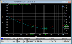
swapping various 6HJ5 tubes I was able to get the THD+N down to 0.036% at 1W -- this overstates THD% as the power supply spurs are greater than the harmonics. With careful adjustment of the balance potentiometer, THD+N was more than halved.
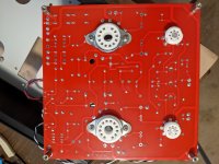
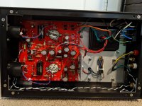
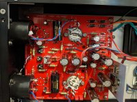
i replaced the original cap multiplier and regulator MOSFETs with FDPF7N60NZT -- an insulated TO-220 package. As Pete suggests, mounting the MOSFETs on the heatsink is tricky -- I just threaded and soldered 24 awg wire and soldered them up, bending the leads 90 degrees and attaching to the wires. The insulated package must have thermal grease.
i replaced the original cap multiplier and regulator MOSFETs with FDPF7N60NZT -- an insulated TO-220 package. As Pete suggests, mounting the MOSFETs on the heatsink is tricky -- I just threaded and soldered 24 awg wire and soldered them up, bending the leads 90 degrees and attaching to the wires. The insulated package must have thermal grease.
Attachments
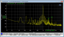
swapping various 6HJ5 tubes I was able to get the THD+N down to 0.036% at 1W -- this overstates THD% as the power supply spurs are greater than the harmonics. With careful adjustment of the balance potentiometer, THD+N was more than halved. i replaced the original cap multiplier and regulator MOSFETs with FDPF7N60NZT -- an insulated TO-220 package. As Pete suggests, mounting the MOSFETs on the heatsink is tricky -- I just threaded and soldered 24 awg wire and soldered them up, bending the leads 90 degrees and attaching to the wires. The insulated package must have thermal grease.
Attachments
well done .... great project you must be pleasedProject done!
And, oh yes, they sound sweet...
Thank you all for the patience and precious advice!
Now some logos and stickers on it, and that's all folks! View attachment 919126 View attachment 919127 View attachment 919128 View attachment 919129
Hi everyone, I hope you are all safe and well. Greetings from the UK
I've just started a build of these (after having the boards sitting around for a few years)
I just have a few questions/ideas I would like to share
The first is related to tubes.
I am planning to use 6CB6(A) Pentodes (6GU5 are pretty much impossible to get in the UK) Are they a good swap?
I don't suppose anyone knows of a good replacement for the Sweep Tubes?
If not I will order some from the States, but the cost, when postage is added, is astronomical.
The second point is regarding design.
I am planning on wiring the Tube Sockets back to the PCB rather that soldering them in directly.
Can anyone see any issues with this? Also what guage wire is needed?
I started populating one board yesterday and it was the first time I'd soldered in many years
Just waiting on availability of some parts from Mouser, and need to find alternatives for some other parts
Going to use the Fender 290FEX for power (thanks Pete for the advice)
Really excited for this project
Joe
If you plan to wire output tube sockets back to the PCBs (and I don’t see any problem with it if you are cognizant of any grid-stopper/oscillation issues) then you have the freedom to choose any appropriate sweeptube, especially if you are willing to use those with plate top-caps.
I don’t know a specific “replacement” for 6HJ5, but there are several that will work well in the ”50 watt Engineers Amp”. Member “smoking-amp” tested and wrote about a lot of them in the Tube/Valve sticky ”Those magnificent TV tubes”, see link below. It is a matter of finding a source at a price that you find reasonable. As a last resort, JJ now manufactures a fresh octal-based EL509 without a topcap. Good luck.
https://www.diyaudio.com/community/search/143561/

The amp was originally designed to use 6CB6 pentodes. Should still work wellI am planning to use 6CB6(A) Pentodes (6GU5 are pretty much impossible to get in the UK) Are they a good swap?
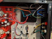
For the heaters I suggest 18 AWG (1 sq. mm) copper wire (depending on what sweeptube you choose - 6LW6 has 2.65 amps heaters). The rest of the wires carry little current, so anything thicker than 24 AWG (.25 sq. mm) is fine. Watch the voltage and heat ratings of the insulation though, especially if you use a topcap tube. I typically use teflon or similar insulation for this reason.I am planning on wiring the Tube Sockets back to the PCB rather that soldering them in directly.
Can anyone see any issues with this? Also what guage wire is needed?
Enjoy the experience of getting back into slinging solder! Best wishes and let us know how it worked out.I started populating one board yesterday and it was the first time I'd soldered in many years
Really excited for this project
Joe
Last edited:
Had I to do it all over again, I would have wired the tube sockets back to the PCB rather than soldering them in place. This allows for some experimentation.
Make sure that the screen voltage regulator and B+ cap multipliers are working before inserting the tubes. I had a bad solder connection on one of the zeners and fried a pair of 6HJ5's. 6HF5's with plate cap would work but since they were used for ham radio transmitters (like Drake 2NT) they are getting expensive.
The balance pot really does allow one to trim the THD%, --
Finished my build.
I mostly stuck to using the parts called out in the BOM but I had to make some substitutions for some caps that were out of stock and some of the KOA resistors that were obsolete and out of stock.
At C5 and C6 I used Mundorf MCap Supreme Silver Gold Oil capacitors. I’ve had good experiences with these caps in other gear that I use.
One other substitution that I made is to use a 3.15A slow blow fuse in the power inlet. I started out using the 2A slow blow called out in the BOM but these were blowing on every 2nd or 3rd power up. The 3.15 fuses haven’t blown after several power ups.
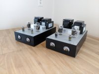
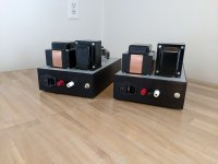
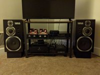
The chassis is from Landfall Systems and it’s the same one that Pete used in his build, including the color scheme. The happy coincidence is that the colors match my NS-1000M speakers perfectly. It’s an excellent chassis. The guys at Landfall were great to work with.
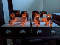
Everything worked on first try. I was able to set the bias and balance easily with the first set of tubes that I installed. The tubes are Sylvania 6GU5 and Raytheon 6HJ5.
The sound quality is stunning. It’s very alive, euphonic, and engaging. The highs are smooth and clear. Vocals are natural sounding. Bass is deep, tight and articulate. Very big sound image. The speakers disappear. Separation and “air” around the instruments is excellent. Hooked up to my NS-1000M’s, the sound is ultra-transparent. I don’t want to stop listening.
Kudos to Pete for such a great design.
I mostly stuck to using the parts called out in the BOM but I had to make some substitutions for some caps that were out of stock and some of the KOA resistors that were obsolete and out of stock.
At C5 and C6 I used Mundorf MCap Supreme Silver Gold Oil capacitors. I’ve had good experiences with these caps in other gear that I use.
One other substitution that I made is to use a 3.15A slow blow fuse in the power inlet. I started out using the 2A slow blow called out in the BOM but these were blowing on every 2nd or 3rd power up. The 3.15 fuses haven’t blown after several power ups.
The chassis is from Landfall Systems and it’s the same one that Pete used in his build, including the color scheme. The happy coincidence is that the colors match my NS-1000M speakers perfectly. It’s an excellent chassis. The guys at Landfall were great to work with.
Everything worked on first try. I was able to set the bias and balance easily with the first set of tubes that I installed. The tubes are Sylvania 6GU5 and Raytheon 6HJ5.
The sound quality is stunning. It’s very alive, euphonic, and engaging. The highs are smooth and clear. Vocals are natural sounding. Bass is deep, tight and articulate. Very big sound image. The speakers disappear. Separation and “air” around the instruments is excellent. Hooked up to my NS-1000M’s, the sound is ultra-transparent. I don’t want to stop listening.
Kudos to Pete for such a great design.
Attachments
-
 PXL_20220320_230447435.jpg316 KB · Views: 155
 -
 PXL_20220327_194804281.jpg444.2 KB · Views: 148
 -
 PXL_20220327_194813415.jpg487.9 KB · Views: 146
 -
 PXL_20220327_194823446.jpg439 KB · Views: 178
 -
 PXL_20220327_201233373.jpg338.6 KB · Views: 176
 -
 PXL_20220327_201718169.jpg293.1 KB · Views: 172
 -
 PXL_20220401_232918811.NIGHT.jpg322 KB · Views: 159
 -
 PXL_20220402_003307363.jpg459.8 KB · Views: 162
I went through quite a few 2A fuses as well so I put another inrush limiter in the B+ line. After that all is well.One other substitution that I made is to use a 3.15A slow blow fuse in the power inlet. I started out using the 2A slow blow called out in the BOM but these were blowing on every 2nd or 3rd power up. The 3.15 fuses haven’t blown after several power ups.
Kudos to Pete for such a great design.
Yes, hat tip to Pete for a great design!
I went through quite a few 2A fuses as well so I put another inrush limiter in the B+ line. After that all is well.
Did you add another CL140 in series with the one at RT1?
I think that I put a different one in the transformer primary line. It wasn't an Amphenol.Did you add another CL140 in series with the one at RT1?
In any regard, when you use an inrush current limiter it's important to consult the datasheet and look at the min/max current brackets. Too little current for the device may cause it to run out of safe-operating-area.
One other substitution that I made is to use a 3.15A slow blow fuse in the power inlet. I started out using the 2A slow blow called out in the BOM but these were blowing on every 2nd or 3rd power up. The 3.15 fuses haven’t blown after several power ups.
I think that I put a different one in the transformer primary line. It wasn't an Amphenol.
In any regard, when you use an inrush current limiter it's important to consult the datasheet and look at the min/max current brackets. Too little current for the device may cause it to run out of safe-operating-area.
I went back to using the 2A slo-blow fuses and added a CL-90 inrush limiter on the primary. No more blown 2A fuses.
- Home
- Vendor's Bazaar
- 50W monoblock "Engineers Amp"