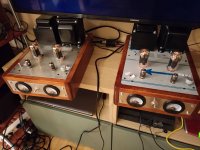
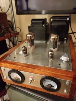
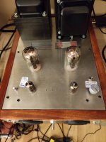
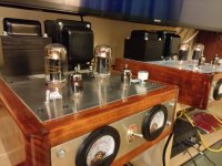
And nothing, changed a lot doing tests on driver's plate voltage (so plate R), Schade feedback resistors value, screen grid voltage...
that crossover distortion is always there, bumps in at 12W...
I discovered that a slightly lower screen grid voltage (140V) helps with biasing colder... but yet, the c.o. distortion gets better at around 80mA bias current...
these are my working points:
B+ 550V
6GU5 plate voltage, 200V
Screen grid voltage, 146V,
OPT 100W PP 3300 Ohm built by specification
control grid voltage, around -32V, according to biasing...
6HJ5 cathode voltage (bias) 0.36 for one, 0.44 for the other one, (so dissipation lies around 22W
Driver plate resistors 52K
Schade fb resistors 470K
Could please somebody help me figuring out something?
Thanks
Thing is, to get 150v on g2, i needed to change some resistances:
The heatsinked one went to 220k instead of nominal 5k
If you had to change the 5K resistor in the screen grid regulator to 220K, then something in your regulator circuit is broken. With a 220K resistor you will find that your screen grid voltage drops severely when you drive the amp, and this will result in LOTS of distortion.
Put back the 5K, and find out what's wrong in the regulator (without output tubes in the amp) before going any further.
The likely cause for problems in the regulator is a shorted mosfet, or an open zener diode. As I once found out, accidentally putting a regular rectifier diode in place of one of the zeners will do it too.
Ok thanks George...
And now, last new, the plate voltage is dropping to zero in the feedback driver tube...
Desoldered and inspected the involved components, they're ok, tried voltages without tubes, they're fine... Not that I burned also the ccs?
I don't know what's happening with this amp... It started like an easy task, now it's becoming a nightmare...
Thing is, I've now a b+ of around 530V. Schematic has some 100V less entering the heatsunk resistor... Still the 5k will be working?If you had to change the 5K resistor in the screen grid regulator to 220K, then something in your regulator circuit is broken. With a 220K resistor you will find that your screen grid voltage drops severely when you drive the amp, and this will result in LOTS of distortion.
Put back the 5K, and find out what's wrong in the regulator (without output tubes in the amp) before going any further.
If you had to change the 5K resistor in the screen grid regulator to 220K, then something in your regulator circuit is broken. With a 220K resistor you will find that your screen grid voltage drops severely when you drive the amp, and this will result in LOTS of distortion.
The likely cause for problems in the regulator is a shorted mosfet, or an open zener diode. As I once found out, accidentally putting a regular rectifier diode in place of one of the zeners will do it too.
you were right.
a mosfet was shorted, all diodes and zener fried.
i guess in the first testing i exceeded shortly the 600V figure. Still, is a voltage of around 540V safe for the mosfets and the zener in chain?
thank you,
Mike
What could be a plug in substitute of this FQPF8N60CF ?Why not use a MOSFET with a higher voltage rating? I use 900 Volt MOSFET’s for 600 VDC out. It’s good to be on the safe side as there could be (and probably will be) spikes on your high voltage rail.
MOSFET’s react on spikes (and get fried).
Regards, Gerrit
Found, of course the FQPF8N90C
Last edited:
And what about the zeners chain? They keep their value of 50V, 0.5W dissipation?Why not use a MOSFET with a higher voltage rating? I use 900 Volt MOSFET’s for 600 VDC out. It’s good to be on the safe side as there could be (and probably will be) spikes on your high voltage rail.
MOSFET’s react on spikes (and get fried).
Regards, Gerrit
I guess your zeners will survive when used with a MOSFET source follower. The series resistor from your raw DC to the zener chain can be 10K or higher. However, the cooler, the better. If you can find zeners with a higher rating they will probably run cooler and show less voltage drift.
I have used higher voltage zeners too, including values from 100 up to 200 Volts, but then allways with a higher rating of 3 Watt (or even more).
Regards, Gerrit
I have used higher voltage zeners too, including values from 100 up to 200 Volts, but then allways with a higher rating of 3 Watt (or even more).
Regards, Gerrit
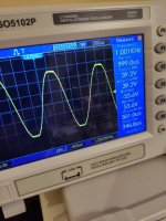
Ok friends, so far so good... For a monoblock at least. (Fig 1.) A little more than 100W on 8 ohm load.
Second monoblock, however, is bad.
Symptom is that with a lov level of input signal, i get very low output, and cathode current rising to the stars...
For the working mb:
INPUT. OUTPUT(Rms) CATH CURR
0.5Vpp. 8V. 0.4V on both
1 Vpp. 15V. 0.64V (64ma) on both
1.5Vpp. 21.2V. 0.9 (90ma) on both.
The one under testing gives:
INPUT. OUTPUT. CATH CURR
0.5Vpp. 2V rms. 0.8V (80ma) on both...
Nevertheless, the power transformer buzzes and rattles...
Measured voltages are stable and spot on and on line with the working mb.
I swapped all the electrolytics on the b+ path, no effect, swapped the ones on the driver plate path, no effect.
I swapped the tubes with the set mounted on the working one, no effect.
Plate voltage on the power tubes is 520v,
Biased at 35 mA (both mb)
Plate voltage on drivers 6gu5, is 220V-ish.
C- circuit stable and working.
Screen grid circuit spot on on 150V.
I have no ideas left... At this point I could try with the working mb output transformer... But don't think it's that...
Any hints please?
Thanks!

Forgot to mention...
Transformers winded in italy at Raoli's
Power, 135wpc before clipping.
Bandwidth til 20kHz (-3dB)
Distorsion? Have no audio analyzer, yet the scopes fft looks promising...
Gnfb optimized for -6dB, changed only the mica cap to 100pf from 33pf... Was ringing...
Schade Feedback resistors Up to 330k
Drivers plate resistors up to 47k
Plate voltage on 6hj5 525V
Plate voltage 6gu5 220V
What else...
OT is 3300k with 0-4-8-16 ohm outputs
Power transformer 400-70-0-400
All optimized for EU 50Hz mains
Bias pots voltage? GU50 viability?
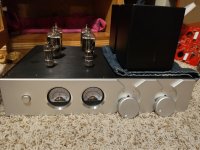
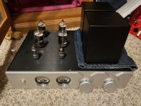
So here's my planned build. I won't be using two potted transformers like in this pic. It will be the Hammond 290FX + filament transformer with the potted Tribute Audio opt in the back.
Do the bias pots hold high voltage? I am planning on running the bias pots to the knobs in the pics. However, since every large bias pot has a metal shaft and the knobs are metal I want to be sure this is safe.
Shown here are 6GY5's. I have a lot of them along with EL509's however the high voltage plate cap scares me especially with a puppy and hopefully kids of my own in the future. 21VJ6's would work however I am also looking at the GU50. I can't find plate resistance or gm values of this Luftwaffe/USSR vacuum tube. How would the GU50 work with 4.3K opt compared to the 6GY5/21JV6 in this design?


- Home
- Vendor's Bazaar
- 50W monoblock "Engineers Amp"
 Please do not quote the entire post just above yours. This forum does not use that format. The software was changed to make it more difficult.