Since the time of the good old PL81 I can't remember any sweep tube here in Europe without plate top cap. And this is for good reason, I think.
Best regards!
xL508?
No top cap, 12W rated.
If I didn't have so many projects fighting for bench time already, I'd try them out.
25HX5 14 Watt EL/PL36 equiv. with no top cap.
21LG6A is a good $4 sub for 6HJ5
8136, 6DK6 and 6EW6 are good high gm subs for 6GU5 and 6CB6
By the way, do you know other 6hj5 substitutes at a human price?
xL508?
No top cap, 12W rated.
The EL508 / PL508 is not a sweep tube but a tube for vertical deflection circuits (Vap max. = 2.5 kV).
Ok, Friends, I've travelled the world to learn I must return
From diyaudio with love...
Who's wishing to sell me 4 or 5 6hj5 (possibly not 40$ each) ?
Is there a forum market section?
Thanks
6HJ5 12 Pin Compactron Beam Power Tube
$10 here. Waiting on our favourite auction sites can also be useful - probably worth checking job lots of compactrons .
6HJ5 12 Pin Compactron Beam Power Tube
$10 here. Waiting on our favourite auction sites can also be useful - probably worth checking job lots of compactrons .
Wow, huge thanks! Already ordered
6HJ5 12 Pin Compactron Beam Power Tube
$10 here. Waiting on our favourite auction sites can also be useful - probably worth checking job lots of compactrons .
many years back i got those for just U$1 each at Rogalskie's...
If the current goes up when connecting a particular speaker, with no audio, it's likely that it is oscillating due to some reactive component of the load. Usually if you place a dummy resistor load of between 20 and 100 ohms across the output, it fixes it...
Pete
Sorry I know this is an old thread but just to clarify; the resistor should go across the speaker side of the output transformer?
Ok, so, a first working moniblock build is done... 530v on plates, 150on g2s, biased at 35mA... Yet when cranking up the input on signal gen i get some crossover distortion? Couldn't bias any hotter, I'm already a 20-wattish in there...
First 2 pictures, crossover distortion,
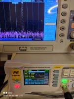
3rd pic, fft at 1W, 8ohm, 1khz tone,
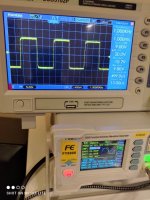
4th, square wave 1khz 20Vpp
5th, 10khz 10Vpp....
All on 8ohm dummy output...
What about that crossover distortion?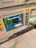
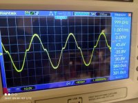
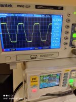
First 2 pictures, crossover distortion,
3rd pic, fft at 1W, 8ohm, 1khz tone,
4th, square wave 1khz 20Vpp
5th, 10khz 10Vpp....
All on 8ohm dummy output...
What about that crossover distortion?


That's clearly very excessive crossover dist. Looks like the top of the sinewave is not conducting for as much as the bottom. I would check the grid drives on the tubes to see if they look OK and equal, and check the DCV on the screen grids to see if they are equal and correct V. If alright, then I would suspect some component is wrong somewhere. Could try another tube too.
I'll have a look later, voltages are all correct,and bias is right on both, at about 20W dissipation...
Curiously, in a batch of 5 tubes, 2 were not working, 2 are these on the rig, one is not tested....
However I got shipped 6 other tubes from rogalsky's, I'll have a test with them... Later...
El Sid, nice rig!
Curiously, in a batch of 5 tubes, 2 were not working, 2 are these on the rig, one is not tested....
However I got shipped 6 other tubes from rogalsky's, I'll have a test with them... Later...
El Sid, nice rig!
That's clearly very excessive crossover dist. Looks like the top of the sinewave is not conducting for as much as the bottom. I would check the grid drives on the tubes to see if they look OK and equal, and check the DCV on the screen grids to see if they are equal and correct V. If alright, then I would suspect some component is wrong somewhere. Could try another tube too.
Thank you smoking, what do you mean exactly with "I would check the grid drives on the tubes to see if they look OK and equal" ?
Visually inspect ?
on grids there are the usual 1k grid stoppers...
Another question: during my test i got a very hot bias, and the tubes, one at a time, had a sudden blue/whitish glow, that disappeared in a moment... I guess I momentarily exceeded the 24W power limit... Bias was over 100mA cathode current... Does that glow mean death?
I still can use them though
I still can use them though
The tubes may be gassy. Running them at reduced power for 1/2 an hour may get rid of the gas by gettering. A gassy tube could be causing the problems too.
If that turns out to be the case, then I would get some 6HD5 tubes from Vacuumtubes.net ( $3), they test their tubes before shipping them.
If that turns out to be the case, then I would get some 6HD5 tubes from Vacuumtubes.net ( $3), they test their tubes before shipping them.
Last edited:
So, i tried i couple of things...
New 6hj5, new 6gu5 drivers.
I kept Vg2 at around 150V,
B+ 520V
Bias around 40mA on power tubes...
No, the crossover distortion won't get away...
It looks like they need more bias, like 0.8/0.9V at the cathodes (80/90mA, that's however too much, we're at 40W !)
I could try some 6ew6 as driver, i could try a dozen more volts on B+...
I mean, i get this distortion with an input AC voltage bigger than 1 V, the amp outputs 10V RMS (so in the region of 13 W power).
Double checked components, they look right...
More than that, I've got no more ideas to test...
Thing is, to get 150v on g2, i needed to change some resistances:
The heatsinked one went to 220k instead of nominal 5k,
The voltage divider one up to 220k instead of 330k.
Looks like the B+ is way greater than the spec one.
Perhaps I got wrong this?
Should I have changed accordingly also the Schade Feedback resistors, those with 220k?
The heatsinked one went to 220k instead of nominal 5k,
The voltage divider one up to 220k instead of 330k.
Looks like the B+ is way greater than the spec one.
Perhaps I got wrong this?
Should I have changed accordingly also the Schade Feedback resistors, those with 220k?
- Home
- Vendor's Bazaar
- 50W monoblock "Engineers Amp"
