Have you tried measuring with the probe tip at the same point as the ground for the probe? This will tell you if those spikes really are over the resistor or if they are just common mode noise.
Maybe you could parallell a couple of film resistors instead of a wirewound to lower inductance?
Maybe you could parallell a couple of film resistors instead of a wirewound to lower inductance?
Hi Megajocke,
I have put two 0.47R film resistors in parallel to sense the current and now the current mode control works fine; there was also a measurement error....
If I measure the voltage across the resistor I see a ramp starting from 0V to 1V.
I have changed my output inductor with 35turns on a gapped RM14 core in N41 material. The inductance is 500uH.
I still have problems with my opto feedback loop and I have noticed that at moderate loads (around 150mA) it is still in discontinuos mode. If I decrease the input voltage from 230Vac to around 190Vac it goes in continuous conduction mode and the sounds coming from the transformer disappears and the output is still reguated to 85V. The loop seems to be stable in this condition
I don't understand what is happening, a current mode controlled converter should not sustantially change its transfer function between CCM and DCM so why my loop is stable in CCM and not in DCM???
Is there any problem in running the converter in DCM at moderate loads?
Please help.
thank you
ciao
-marco

Hi Mag,
Interesting project.
Something that has been mentioned on this site before is to add some snubber' to the gate drive at LSG, HSG, something like 2.2nF and 30 ohms. This really helps clean up the drive signal of the fet, typically switch on, removes some of the high frequency content.
Also a snubber, d c r across your output diodes will help control any ringing that may be there, d13 d14, that will be trial and error.
Also does C17 affect your loop stability?
I have used these driver chips and assuming your system is stable, current sense working, they work very well.
When your power is up I will be interested in how the system reacts to load changes.
Also what does the VCC voltage look like.
Dibley
500µH seems excessive for that frequency and power level, there won't be much current slope for the controller to regulate on so noise could be a problem. The output capacitance is also huge (which is probably good) so you could decrease the inductane to get a little more ripple current and better margin for noise in the controller.
Is that form of compensation really right for a forward converter? The output capacitors make the output lag 90 degrees behind current command at low frequencies and it looks like the compensation network will have phase lag down to very low frequencies too, possibly making the loop unstable. IIRC one has to put a limit on the gain at low frequencies for the feedback network.
Maybe the big inductor hides the instability in continuous mode.
Hi megajocke, I think you are right.
Now I have changed my feedback loop as follows:
C19=1uF R20=82k R14=2k2 C17=10nF.
This gives me a loop BW of 1500Hz and a phase margin of 130°.
The feedback zero is located at 1Hz and the feedback pole at 5.6kHz. There is also a second pole at around 10kHz due to the optocoupler.
The converter has a pole at 1.25Hz (1/Rl*C0), assuming 500W load and a zero at 720Hz (1/ESR*C0) (assuming 50mR of capacitors ESR).
Now the loop is stable at moderate loads (10W) even when the converter is still in DCM.
At very light load (around 2W) it is still unstable.
I was thinking that increasing the output inductance will put the converter in CCM even with light load but it is not the case. It seems to work best with inductance values around 50uH.
Now the problem is: this converter will power a class-D audio amp, the minimum load will be for sure less than 10W. How can I supply the amp if the converter is unstable when the amp is idling??? please help!
@Dibley
Thank you for you interest in my project. By now I have very clean gate drive waveform, I don't think I need a snubber there.
The current control loop seems to work well, there are no more ugly spikes across the sensing resistor.
C17 combined with the internal FAN7554 resistor (3k) create a pole in the feedback loop (1/C17*3k). You have to take care of this and also the pole created by the optocoupler for the feedback stability.
I have not yet tried the dynamic response of the converter, by now I still have troubles with the feedback.
ciao
-marco
Two switch forward converter
I see you have worked thru most of your problems but I might suggest that you obtain a copy of "Switch-Mode Power Supplies Spice Simulations and Practical Design" authored by Christophe Basso as this addresses all your problems including how to stablize the feedback in the current mode DCM and CCM of the two switch forward converter and also how it can switch from one to the other and you can also simulate your designs before you build and test them (chapter 8) pay attention to fig 8-13A. Read 8.3.1 about charging your boot cap. You are wise to use this topologly as HB in current mode presents some unique problems that can be hard to debug rather I would choose FB just a few more parts but without the added problems. You can extend the two switch forward easily to 1kW and I might suggest IGBT over mosfets. I am not prompting books just an addition to your reading list.
chas1
Hi all,
I am still in troubles with my smps and I don't understand why.
Now the smps is stable but as soon as the load increase above 100W it swithes off and tries to restart.
I have done the following modifications:
1) Changed the feedback loop, now BW=1kHz and phase margin=80°.
2) Clamped the maximum duty cycle on the FAN7554 to 40%changing the values of RT and CT.
3) Replaced IR2110 with a 1:2:2 transformer gate drive + output buffers.
4) Added a low pass filter on the current sense line to compensate the zero due by the inductance of the current sense resistor.
After all those modifications basically the behaviour is always the same, even if I open the feedback (removing the opto) and I apply a voltage to the FB pin the system shuts down under high load.
The most strange thing is that the smps "works" only with an output buck inductance up to 40uH, if I increase such inductance the smps shuts down even at less load.
From the Spice simulations everything seems fine but in the reality something is wrong.
I am suspecting that the PWM controller does not work properly due to switching noise, is it possible?
Has anyone of you tried the FAN7554 in a forward topology.
Thank you very much
ciao
-marco
Simulation & Schematic
Mag
Might be able to help but need schematic, I have simualted my fwd using LTspice . The other about inductor and output cap both should be sized for the application not to compensate the controller. The controller is compesated by the selection of the fxo and the type of feedback type II for current mode and type III for voltage mode. A good phase margin is between 55 deg to 70 deg for both.
chas1
What does the gate drive transformer drive look like? Can you post a schematic?
It needs to be a bit special or the transformer will saturate. Sounds likely as the converter seems to be shutting down when duty cycle increases. (Bigger output inductor -> larger duty cycle at a certain load when in discontinuous mode)
It needs to be a bit special or the transformer will saturate. Sounds likely as the converter seems to be shutting down when duty cycle increases. (Bigger output inductor -> larger duty cycle at a certain load when in discontinuous mode)
Question's
Is the schematic posted the supply in question, unless I miss something it is rated for 500 watts +/- 85VDC at about 3 amps. What type of load ? The total inductance I think is high, below 200uH in each leg should be sufficent. What are the ripple requirements. Do you mind sharing the method you use to calculate your compensation and why you picked a 1khz fxo? You might add a cap across the opto's transistor (add a pole) and instead of the resistor cap combo at the tl431 just use a cap for the zero there, tie the resistor for the opto diode to the +85 output inductor's input using a zener to protect opto and tl431 and then the voltage divider to the +85 out. I haven't used this controller IC but most are the same as far as current control you have to have a good spike filter for the ramp input also slope compensation must not load the osc. Checkout the startup circuit as this could be a problem sometimes.
Output inductor calculation I use/
Lo(min)=(Vsec(min)-Vout)*toff(min)/1.4Iout(min)
Vsec(min) is 1.1 Vin(min)*(Ns/Np) and a good guess for toff(min) is about 30% of 1/freq of operation. (1/100kHz)*30% for example.
Another from Pressman on pg 166 Lo=.5Vout*T/Iload
So for a 2kW supply Vout = 200VDC @10A at 50kHz this would work out to 200uh with half in the postive out ant half in the negative out.
Maybe another controller
mag
I think you might want to consider another controller IC which will simply your design and make it more robust. Look at the datasheet for the NCP1216A, Your parts count will be lower and you should be able to cleanup the design with very few changes to pcb layout.Another IC is UC3825 TI's website has a good appnote that can be scaled.
chas1
hi Chas1 and megajocke,
The feedback is compensated with a type II amplifer built with the tl431.
Phase margin is set at 80deg and fxo is 1kHz. In simulation for every load conditions is stays above 55 deg.
The transformer is built around a gapped RM8 core, 20turns for primary, 40+40 turns for both secondaries (bifilar). Primary inductance is 250uH and Bmax is 47mT. I don't think that it is saturating.
The SMPS will power a class-D audio amplifier. I have done all my calculations for maximum 5A on both outputs.
I use the k-factor method explained by C. Basso in his book. I have simulated the converted in open loop , then applied the k-factor method to find out where to place the pole and the zero.
I have also measured the opto (CNY17), it gives me a pole at 15kHz when loaded with a 3k pullup.
I dont't think that this method will work, it can work for low voltage smps. If I power the opto led+tl431 direcly trough the 85V rail (usually before the buck inductance) you will have a voltage on the 431 cathode well above its maximum rating. If I clamp that voltage with a zener for example at 15V the loop will work in DC but the zero disappears. The zerer with its low dynamic resistance will short in AC the connection to the 85V rail. (look at figure 3-37 of Basso book and you will see that K1 becomes =0). I have added another resistor in series with Czero with the same value of Rupper to generate a zero.
This was the main problem in getting my feedback stable but now I am quite sure that it works as expected.
This is possible, but I am not using always the same core. What is strange is that in happens also with around 1A of output current (by now only the positive rail is used for testing), if I calculate the B_DC in the inductance it will be well below the Bsat.
I know that controller and I really like it, the problem is that is not readily available for me to do some test with it.
Thank you for support
ciao
-marco
The controller is compesated by the selection of the fxo and the type of feedback type II for current mode and type III for voltage mode. A good phase margin is between 55 deg to 70 deg for both.
The feedback is compensated with a type II amplifer built with the tl431.
Phase margin is set at 80deg and fxo is 1kHz. In simulation for every load conditions is stays above 55 deg.
What does the gate drive transformer drive look like? Can you post a schematic?
The transformer is built around a gapped RM8 core, 20turns for primary, 40+40 turns for both secondaries (bifilar). Primary inductance is 250uH and Bmax is 47mT. I don't think that it is saturating.
, unless I miss something it is rated for 500 watts +/- 85VDC at about 3 amps. What type of load
The SMPS will power a class-D audio amplifier. I have done all my calculations for maximum 5A on both outputs.
you mind sharing the method you use to calculate your compensation and why you picked a 1khz fxo?
I use the k-factor method explained by C. Basso in his book. I have simulated the converted in open loop , then applied the k-factor method to find out where to place the pole and the zero.
I have also measured the opto (CNY17), it gives me a pole at 15kHz when loaded with a 3k pullup.
You might add a cap across the opto's transistor (add a pole) and instead of the resistor cap combo at the tl431 just use a cap for the zero there, tie the resistor for the opto diode to the +85 output inductor's input using a zener to protect opto and tl431 and then the voltage divider to the +85 out.
I dont't think that this method will work, it can work for low voltage smps. If I power the opto led+tl431 direcly trough the 85V rail (usually before the buck inductance) you will have a voltage on the 431 cathode well above its maximum rating. If I clamp that voltage with a zener for example at 15V the loop will work in DC but the zero disappears. The zerer with its low dynamic resistance will short in AC the connection to the 85V rail. (look at figure 3-37 of Basso book and you will see that K1 becomes =0). I have added another resistor in series with Czero with the same value of Rupper to generate a zero.
This was the main problem in getting my feedback stable but now I am quite sure that it works as expected.
Hmm, saturation of the inductor could also be the problem if you are varying inductance on the same core saturation current will change with changed inductance.
This is possible, but I am not using always the same core. What is strange is that in happens also with around 1A of output current (by now only the positive rail is used for testing), if I calculate the B_DC in the inductance it will be well below the Bsat.
I think you might want to consider another controller IC which will simply your design and make it more robust. Look at the datasheet for the NCP1216A
I know that controller and I really like it, the problem is that is not readily available for me to do some test with it.
Thank you for support
ciao
-marco
Gatedrv
mag
Yes , you are right about circuit connections an oversight on my part. You have a good reference I also have this book and find it useful for simulating certain circuits but most of my work is with breadboards. I would like to suggest a read of "Design Review A 300watt 300kHz Current mode Half-Bridge Converter with Multiple Outputs Using Couple Inductors author Roger Adair " It is part of the TI series of files topic 6. The only reason I mentioned changing to a different controller is after looking at the datasheet for the Fan I see a lot of disclaimer's and that bothers me as current mode control needs to be as simple as possible I think to work properly and by the way a HB using the the MC33025 in current mode does not require any hacks to work around Flux walking as that is taking care of by evaluating the transformer current on a pulse by pulse basis.
chas1
mag said:hi Chas1 and megajocke,
The transformer is built around a gapped RM8 core, 20turns for primary, 40+40 turns for both secondaries (bifilar). Primary inductance is 250uH and Bmax is 47mT. I don't think that it is saturating.
What matters is how it is driven.
What kind of DC blocking and DC restoration circuit do you use?
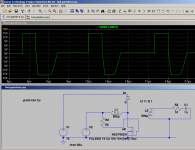
The attached picture is an example of how the gate drive transformer can be driven. (The MOSFET is a pretty small fet, left voltage source = driver power supply, right voltage source = PWM chip output).
Another possibility is using a DC blocking capacitor and DC restoration clamps on the outputs of the transformer, but that method might have problems when duty cycle is changing fast.
The waveform shows output voltage of gate drive transformer.
Attachments
Here is an example of one with DC blocking/restoration:
http://www.eettaiwan.com/ARTICLES/2000JUN/2000JUN19_AMD_AN465.PDF?SOURCES=DOWNLOAD
I'd probably add zeners to the gate drive cells for protection, but the circuit is pretty OK otherwise.
http://www.eettaiwan.com/ARTICLES/2000JUN/2000JUN19_AMD_AN465.PDF?SOURCES=DOWNLOAD
I'd probably add zeners to the gate drive cells for protection, but the circuit is pretty OK otherwise.
- Status
- This old topic is closed. If you want to reopen this topic, contact a moderator using the "Report Post" button.
- Home
- Amplifiers
- Power Supplies
- 500W offline SMPS