mag said:
Current sense resistor: I have put in parallel two resistors of 0.22R 3W, I have then measured the inductance of that combo with a network analyzer and I got 25nH. Then I have placed a low pass filter to compensate the zero created by the parasitic inductance of the sense resistor (fzero=Rsense/(2*pi*Lsense)=700kHz). A low pass filter with R=2.2k and C=100pF can do the job.
But you also have a current spike in the beginning of the period caused by secondary diode reverse recovery when in continous mode and capacitance of transformer and any snubbers. You probably need to filter even more than just to compensate for the inductance of the sense resistor. Or does the chip have leading edge blanking?
Hi mag,
>>
Can you please clarify the point about the 12V generation? If I remove the diodes D15 and D16 I should also remove the inductances L2 and L3. In this way it becomes a peak rectifier and the winding on the transformer must be changed. What is the advantage of doing this? My TL431 + opto are powered from the +12V output, can a problem on the 12V output jeopardize the feedback stability?
>>
The +/-12V power supply is configured as a buck regulator with two linear reg's. If the power supply goes into current limit mode, the duty cycle will be reduced and the input voltage of the linear regulators will fall. I can imagine this is not what you want. In severe cases your power supply will be ready for the scrap yard in no time.
Using peak voltage rectification, the input voltage of the regulators will be almost constant and independent of the duty cycle. Now the output voltage depends on input voltage (and to some extend the load current). You should design the primary circuit in such way that your power supply will shut down if the input voltage is to low. You can use the eax. supply for that purpose.
L2 and L3 can be removed. Or better, replace the inductors with small value resistors.
Also, you are trying to make gate drive transformers with gapped cores. That won't work.
Regards, Hendrik
>>
Can you please clarify the point about the 12V generation? If I remove the diodes D15 and D16 I should also remove the inductances L2 and L3. In this way it becomes a peak rectifier and the winding on the transformer must be changed. What is the advantage of doing this? My TL431 + opto are powered from the +12V output, can a problem on the 12V output jeopardize the feedback stability?
>>
The +/-12V power supply is configured as a buck regulator with two linear reg's. If the power supply goes into current limit mode, the duty cycle will be reduced and the input voltage of the linear regulators will fall. I can imagine this is not what you want. In severe cases your power supply will be ready for the scrap yard in no time.
Using peak voltage rectification, the input voltage of the regulators will be almost constant and independent of the duty cycle. Now the output voltage depends on input voltage (and to some extend the load current). You should design the primary circuit in such way that your power supply will shut down if the input voltage is to low. You can use the eax. supply for that purpose.
L2 and L3 can be removed. Or better, replace the inductors with small value resistors.
Also, you are trying to make gate drive transformers with gapped cores. That won't work.
Regards, Hendrik
Primary inductance of trans.
mag
I agree the primary inductance seems low to me for an etd44 core set the AL is about 3800nH and you have 36T,therefore 36**2 X 3800E-9 = about 5mH, Is the core gapped or the clips tight,core cracked or I might not be driving my walmart calculator correctly also I note in your sim schematic you have a 200uH inductor in the output filter and the output current is about what I expected 5 amps, or about 1kW give or take for the supply. I will check my results now with a spk model I have as a load and send them to you shortly to see if you agree, I will be using LTspice but plots and schematic will be gif also I am going to jack up the fxo to about 5kHz a conservative figure but I find it works well with the TL431 / opto combo.
chas1
transformer
In fact I have two different transformers (sorry I forgot to tell you).
One is: primary:20t, secondary 18+18t --> N=0.9 Lpri=1.4mH
The second is: primary=36t, secondary 28+28t --> N=0.77 Lpri was never measured but I suppose it is around 5mH from core AL.
The behaviour with both transformer is basically the same.
Thank you, I will try it, but I suppose that I need to divide by two the number of turns of the +/-12V winding, am I right?
No, the IC has no leading edge blanking and this is the main reason than makes me think about changing the controller.
I can try to filter more but how much? Do you have any reasonable figure I can try?
Secondary side diodes are IXYS DSEI12-06A, 600V 14A trr=35ns, I think they are ok but please advice.
Why increasing the BW to 5kHz? There is no risk of picking up even more noise?
Thank you very much to all of you for the support! In the next days I will not have so much time to work on this project but as soon as I have some news I will post again.
ciao
-marco
In fact I have two different transformers (sorry I forgot to tell you).
One is: primary:20t, secondary 18+18t --> N=0.9 Lpri=1.4mH
The second is: primary=36t, secondary 28+28t --> N=0.77 Lpri was never measured but I suppose it is around 5mH from core AL.
The behaviour with both transformer is basically the same.
The +/-12V power supply is configured as a buck regulator with two linear reg's. If the power supply goes into current limit mode, the duty cycle will be reduced and the input voltage of the linear regulators will fall. I can imagine this is not what you want. In severe cases your power supply will be ready for the scrap yard in no time.
Thank you, I will try it, but I suppose that I need to divide by two the number of turns of the +/-12V winding, am I right?
But you also have a current spike in the beginning of the period caused by secondary diode reverse recovery when in continous mode and capacitance of transformer and any snubbers. You probably need to filter even more than just to compensate for the inductance of the sense resistor. Or does the chip have leading edge blanking?
No, the IC has no leading edge blanking and this is the main reason than makes me think about changing the controller.
I can try to filter more but how much? Do you have any reasonable figure I can try?
Secondary side diodes are IXYS DSEI12-06A, 600V 14A trr=35ns, I think they are ok but please advice.
I am going to jack up the fxo to about 5kHz a conservative figure but I find it works well with the TL431 / opto combo.
Why increasing the BW to 5kHz? There is no risk of picking up even more noise?
Thank you very much to all of you for the support! In the next days I will not have so much time to work on this project but as soon as I have some news I will post again.
ciao
-marco
Whew
mag
Happy holidays and enjoy them, thanks for clearing up the transformer.Diodes are fine by me .I think after you change the controller IC problems will disappear, while I haven't used this controller(I have a few samples of the mc33025)I am going to order some samples and design it into a supply for a client. Is noise the reason you choose such a narrow bandwidth, I would consider revising that to at least 5-6kHz you could raise that a little but the opto has a pole that must be considered.By the way in Chris's book he has a neat way of simulating the opto pole.
One more question about sim schematic , in the list of paramaters for the model you have L =240u but an inductor of 200u I think both should be the same value?
As far as layout for pcb , Marty Browns book does a good job outlining this important step , I have some kludge breadboards and find as long as I stick to the basic's of keeping bypass caps and other senstive components close to controller I have very few problems, some EMI but with breadboards you will have this.
chas1
mag said:Thank you chas1,
Thank you, I will try it, but I suppose that I need to divide by two the number of turns of the +/-12V winding, am I right?
That's correct.
Perhaps you can run your SMPS open loop on order to find out what is going on. But keep the current limiting alive.
Nice Holiday
Sim??
mag
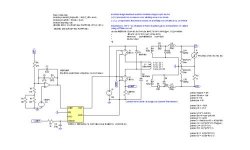
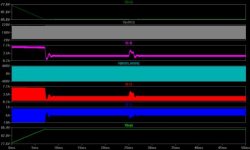
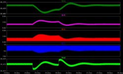
I did a quick sim of the supply using LTspice and below you will find jpg's of results. I included a 2 amp step in the load to check the regulation, also you will see an opamp as external EA but opto should provide the same compensation. This is based on an ETD44 core set with Np=20T and Ns = 10T each (Lp = 1.4mH, Ls 425uH ea)no leakage was including and the DID,MSW model were supplied by a simulation of a Forward by genome. You might want to visit his site, very interesting tutorials for classd and smps. The URL is http://www.overkill.talktalk.net .Below is the jpg's of my sim. If you use LTspice I will provide a zip of all files used for simulation and you can have a play.
chas1
mag
I did a quick sim of the supply using LTspice and below you will find jpg's of results. I included a 2 amp step in the load to check the regulation, also you will see an opamp as external EA but opto should provide the same compensation. This is based on an ETD44 core set with Np=20T and Ns = 10T each (Lp = 1.4mH, Ls 425uH ea)no leakage was including and the DID,MSW model were supplied by a simulation of a Forward by genome. You might want to visit his site, very interesting tutorials for classd and smps. The URL is http://www.overkill.talktalk.net .Below is the jpg's of my sim. If you use LTspice I will provide a zip of all files used for simulation and you can have a play.
chas1
Attachments
Hi All,
after more than 6 months I come back with my project.
The original version has never worked well so I decided to redesign from scratch the power supply in a much better way.
I have also upgraded the power to 1kW.
In attached you will find the schematics; please don't look at the circuits around Q8 and Q9. It was a kind of preload that does not work and makes the two transistors smoke.
I was able to pull out more than 500W from that PSU but after some time the sense resistors started to heat up a lot.
I tried also 1kW and I have reached it from around 2 seconds, after that the sense resistors and the mosfet exploded.
One issue I have found is that the SMPS was running at 100kHz but I designed my transformer to run at 150kHz with Bmax=170mT. Running at 100kHz makes Bmax=255mT. Can 255mT hard saturate an ETD49 in 3C90 material?
It is possible that transformer saturation makes the SMPS exploding?
I suspect there are other issue but I don't have found why.
Please look at the schematics an comment.
Other useful data
-Transformer:
core: ETD49 Ferroxcube 3C90
primariy: 20turns litz wire 200x0.1mm
secondary: 18+18turns (bifilar) litz wire 90x0.1mm
bias: 2turns 0.4mm
secondary 12V: 2+2turns (bilifar) 0.4mm
drive: 2turns 0.4mm
Winding sequence: 1/2 pri (10t) - sec - 1/2 pri (10t) - bias - 12v - drive.
The two half primaries are connected in series.
Primary inductance: 1.6mH
leakage inductance: 8uH (measured at primary with all secondaries shorted)
-Pulse transformer
core E16/8/5 Ferroxcube 3C90
primariy: 46turns 0.23mm
secondary 1: 46turns TEX-E wire 0.2mm
secondary 2: 46turns TEX-E wire 0.2mm
Winding sequence: secondary 2 - primary - secondary 1
Primary inductance: 2.2mH
leakage inductance: 6.5uH (measured at primary with all secondaries shorted)
-Buck inductor
core: toroid Arnold Hi-Flux HF-130125-2
56+56turns bifilar 1mm wire
inductance at no load: 450uH
inductance a 6+6A: 120uH
thank you
ciao
-marco
mag said:
One issue I have found is that the SMPS was running at 100kHz but I designed my transformer to run at 150kHz with Bmax=170mT. Running at 100kHz makes Bmax=255mT. Can 255mT hard saturate an ETD49 in 3C90 material?
It is possible that transformer saturation makes the SMPS exploding?
255mT won't saturate the core, but did you take remanence into account? It looks like 3C90 has 170mT of remanence so 255mT delta-B plus 170mT = 425mT which is about where saturation starts. It gets worse when the core is hot. Remanence is lower at 125mT giving 388mT peak but the core saturates at 350mT.
As you are using peak current mode there shouldn't be any explosions though. I worry about your gate drive which looks strange, are you sure it behaves correctly on fast duty cycle changes? Are you sure the gate drive transformer won't be saturated by dc current through those resistors in parallell with the capacitors?
Also, the RC filter on Isense seems to have a little bit long time constant at 1µs.
Hello Megajocke,
what do you mean by the remanence?
I have calculated B in the following way:
Bmax=Vin_min*Dmax/(N*Ae*fsw),
where Vin_min=217V (ripple of 25% on primary capacitor),
Dmax=48%, N=20, fsw=150kHz and Ae=2.11cm^2.
There is something wrong with this calculation?
I will check the gate driver waveforms and also the current sense filter.
thank you
That looks correct for the flux swing. The problem is that flux doesn't reset to 0mT when drive is removed but to a higher value when drive is unipolar. This is shown graphically in the BH-loop by the intersection between the loop and B-axis. The datasheet I found for 3C90 shows remanence to be about 170mT, lowering to about 125mT at higher temperature.
I don't think this is your primary problem though, one of the nice things about current mode control is that it should tolerate this kind of thing. I'd look at that filter which seems a bit slow and the gate drive circuit which might saturate the gate drive transformer if duty cycle changes abruptly (which is a possibility when using current mode control).
I don't think this is your primary problem though, one of the nice things about current mode control is that it should tolerate this kind of thing. I'd look at that filter which seems a bit slow and the gate drive circuit which might saturate the gate drive transformer if duty cycle changes abruptly (which is a possibility when using current mode control).
- Status
- This old topic is closed. If you want to reopen this topic, contact a moderator using the "Report Post" button.
- Home
- Amplifiers
- Power Supplies
- 500W offline SMPS