Nice !!
You might put your RCA jacks on the topside of the chassis, such that there is 2 inches or less wire span, between the RCA jack and the grid of the D3A !! It is a better design practice, and will usually sound better. Cheers.
Jeff Medwin
i know what you are saying...have done that too...
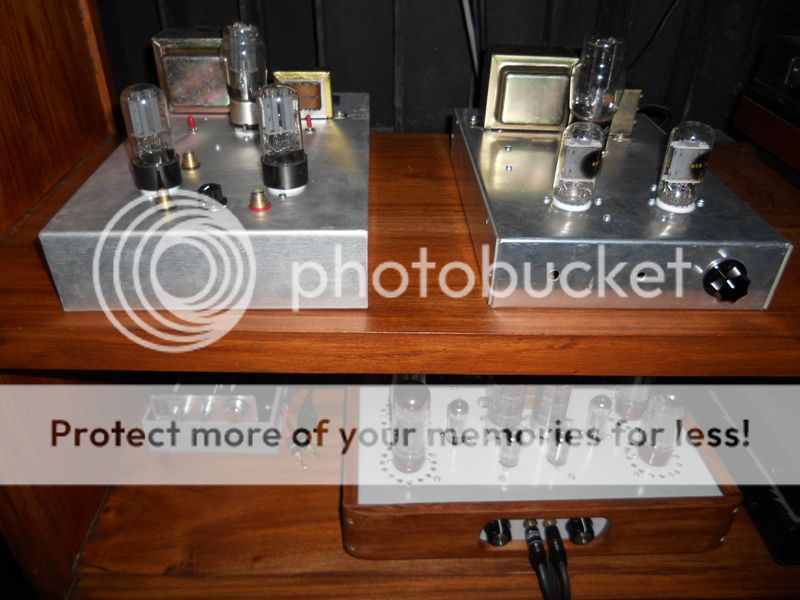
the preamp on the left have input and output jacks very close to the 6H8c tubes....while this amp is not nice to look at, it is the quietest line amp i have done so far...
i know what you are saying...have done that too...
the preamp on the left have input and output jacks very close to the 6H8c tubes....while this amp is not nice to look at, it is the quietest line amp i have done so far...
Way to go !! On the contrary, I think it is beautiful to look at..." form follows function ".
Next, consider punching a 3/4 to 1 inch hole for RCA jacks, and mount them on clear plastic, or bakelite, so that they are even one step further removed from the various EDDY CURRENTs circulating in the metal chassis, it becomes a double insulation. Looks cool too.
Jeff Medwin
Attachments

Last edited:
I may have misunderstood this, but are you saying that the cathode resistance for one triode should consist of two closely matched resistors in parallel? If so, why?drlowmu said:(2) The Cathode of the 12AX7 driver tube requires you to use TWO closely matched paralleled resistors ( Roederstein MK-3 are my favs ) matched to 0.1% of each other, to get maximum DYNAMIC response from the stage, "it just sounds better". I am talking of the Rk value now, of course. Order ten, match two.
I must have misunderstood this!You might put your RCA jacks on the topside of the chassis, such that there is 2 inches or less wire span, between the RCA jack and the grid of the D3A !! It is a better design practice, and will usually sound better.
I may have misunderstood this, but are you saying that the cathode resistance for one triode should consist of two closely matched resistors in parallel? If so, why?
I must have misunderstood this!
You got it correct, two double-the intended final value Rks, in parallel, to ground. This was discovered decades ago by an old friend of mine with his Moore and Franklin MFA Luminescense preamplifiers, which were built by MFA over time, both ways !!! The paralleled R version ATE the standard version, ..... and we don't ever forget such a lesson.
So, there are things I may do in my amp build and I am NOT SURE "why", but I am very sure "it works" from my previous A-Bing, and listening over repeated installations . Its not the science, but rather, the "art" of audio DIY building !!!
I can only "guess" why two closely matched Rks sound more dynamic to me !!!
Here are some "ideas", not meant to be scientific "one iota", that come to my mind :
(1 ) there are two paths for electrons to return to ground, hence instantaneous peak currents, associated with the "pulsed" music signal, do not get easily attenuated.
(2) the super-close matching is "icing on the cake" so to speak, in that one resistor will not "buck" the other's value, in any way. Two in parallel is good, but both closely-matched, is even better sounding.
As a practical example, I happen to like to use Roederstein MK3s, use them in a lot of places. I will always order ten pieces from Michael Percy, and get one ( or maybe two ) closely matched pairs, using my Fluke 8060A DMM.
Additionally, two of the very best tube builders I know and respect, use the paralleled and matched technique on Rks, so I figure ...hey ! I am in great company !!
") Pleased to share this technique, try it for yourself in a well-known piece !!
Pleased to share this technique, try it for yourself in a well-known piece !!- - - - - -
On your question of short ( 2 inches or less ) leads between the RCA jack and the grid of the tube: I will "attempt" a reply.
The signal at the RCA jack input is the lowest level signal in the amp, and it is subject to degradation on its way to the input tube's grid for amplification. There are two types of losses that come to mind off the top of my head ( 1 ) losses in the signal wire itself and (2) losses due to "outside fields", magnetic, etc. interacting with the music signal's propagation down the wire.
I DIY try to counter (1) above, wire losses, by using not one, but two runs of 19 AWG solid silver wire, or perhaps one run of Kimber multi stranded AGSS silver wire to the input tube's control grid. I try to counter (2) above, contamination by extraneous fields, by making the lead length as short as practical, which is 2 inches maximum from RCA jack.
I hope that makes sense to you. I could envision someone trying to "flame" me for this post. Oh well...
Jeff Medwin
Attachments

Last edited:
Here are some "ideas", not meant to be scientific "one iota"
A useful disclaimer, thanks.
This blue chassis ( where I am showing RCA jacks' proximity to input tube ) deserves a brief description.
It is to be one section of a 12AT7 input tube, directly coupled to a triode-connected 6AQ5 finals tube, into Magnequest DS-050 SE Outputs. I imagine about 1.3 Watts output, destined as one of two or three SE DC amps for my new Altec A7-800 modified speaker system.
The 6AQ5, triode-connected, is a "firecracker" of a tube in my opinion. A sleeper. YMMV, etc etc etc.
I also am building for myself two other DIY amps, one with the final tube being a JJ 2A3-40 and a third stereo SE amp using a 6AH4-GT final tube. Three (re) builds ... at one time !!
Jeff Medwin
Attachments

Member
Joined 2009
Paid Member
Jeff, with the additional care going into choice of chassis materials - do you recommend steel or aluminium - or would a non-metal chassis be better ?
Is there a sonic penalty for placing a metal cage over the amp (safety) ?
Well, IMHO, Stainless steel is the best, but impossible to work with on a DIY basis by 99.5% of the DIYers!!!
Regular mild steel has been my favorite choice for DIY builds. Nix on Aluminum.
Mild steel shields well, and is reasonable to Greenlee chassis punch through. Steel however, is magnetic, so all power supply and magnetic parts ( power transformer, chokes, transformers for output ) MUST be raised off of the steel chassis. I use all brass hardware and multiple flat brass washers to space magnetic parts in air, so their own magnetic fields don't couple heavily into the chassis.
I don't mess with non magnetic chassis. Some people do !! Usually prefer to do 14 gauge steel with welded corners for smaller amps, 12 gauge for massive ones. I LOVE powder coating amps. YMMV !!!
As for tube cages, do as you need to, I use none, all VDCs are below deck.
Jeff Medwin
Last edited:
Member
Joined 2009
Paid Member
Regular mild steel has been my favorite choice for DIY builds. Nix on Aluminum.
Thanks Jeff. Plus I was thinking that mild steel provides more strength if mounting some heavy 'iron' on it.
I can only "guess" why two closely matched Rks sound more dynamic to me !!!
Additional thoughts about how parallel resistors might behave differently than a single resistor:
(1) resistors, like all components, have parasitics and are not the ideal parts we sometimes assume (especially in simulations). They have inductance. Placing two resistors in parallel would halve this parasitic inductance.
(2) resistors are also subject to temperature sensitivity. Appropriately chosen paralleled resistors would have less self-heating in each one and less variation in properties with temperature.
(3) some resistors may not be completely uniform or free of defects despite the wonders of modern manufacturing and parallel resistors would tend to reduce the impact of a defect in one of them.
Last edited:
Wow, what a thread... I've followed it for a while now, but geez, there's an awful lot of guessing and imagining on the part of drlowmu.... which basically reflects that there's a lot of fiction, fantasy and snake oil around. No actual facts whatsoever. A few examples follow...
You don't need to imagine what a 6AQ5/6005 will yield in output power, you only need to a look at the published triode plate curves and do a bit of math to get the facts... and it actually does work.
Roederstein MK3s are okay, nothing great, I used them 30+ years ago. There are better resistors around, maybe it's time to move on (i.e., open your wallet)? Paralleling components (resistors, capacitors) is nothing new. Wasn't a great idea decades ago and still isn't. Sonically you're obviously imagining the results as well.
Where does the 2-inch rule originate from for input wire length from a RCA jack to the input grid? Also, AGSS stranded wire is 19ga... how does a single run of this equal two runs of 19ga solid silver? Also, what about the interconnect cable that feeds the amplifier?
If you (drlowmu) want to be taken seriously, at least try to come up with a gram of fact to accompany your kilo(gram) of fiction on your pontifications on how to build anything. Simple question arises... have you ever made any actual measurements on your builds?
Finally, I must be missing something, what is so special about working on three amplifier builds at once?
Regards, KM
If you (drlowmu) want to be taken seriously, at least try to come up with a gram of fact to accompany your kilo(gram) of fiction on your pontifications on how to build anything. Simple question arises... have you ever made any actual measurements on your builds?
Finally, I must be missing something, what is so special about working on three amplifier builds at once?
Search on audioasylum will reveal everything on this subject in a grand scale
Thanks for answering my questions. Your answers were roughly what I expected. I won't be following your advice, as on my planet the rules are different.drlowmu said:I hope that makes sense to you. I could envision someone trying to "flame" me for this post.
It is amusing to see fans now desperately trying to justify daft advice, such as postulating paralleling of resistor parasitics! Relevant to UHF circuits, not audio.
Member
Joined 2009
Paid Member
It is amusing to see fans
ooooh, I've never been called a 'fan' before
Thanks for answering my questions. Your answers were roughly what I expected. I won't be following your advice, as on my planet the rules are different.
It is amusing to see fans now desperately trying to justify daft advice, such as postulating paralleling of resistor parasitics! Relevant to UHF circuits, not audio.
First paragraph :
Q1, just what planet do you live on ??
Second paragraph :
I agree, all I said was I like it better, sounds better to me, and did not hazard too many guesses as to why. In fact, I don't care WHY, all I care about is , "IF it is better, can and should I employ it ?" We get into deep dooty, trying to ascribe "all" the reasons.
Frankly my dear, I don't give a damn ....why !! If I mention a reason or two, its for the reader, not for me to grasp.
IS it ?? .......... Fine !!!
WHY it is ?? ............. Whole different matter.
The first is actual, the second is theoretical.
To the other poster, yes, the SE circuit I use has been measured, very good lab, it does FINE !!
Have a great day !! Mine started off superb, selected a pair of Tan Slacks in my clothes closet this morning, put them on, reached into the left rear pocket, and found three one hundred dollar bills. Heck of a start today, nice big smile !!
Its audio, have FUN, and build something that sounds awesome to you.
Jeff Medwin
Last edited:
What happened to this thread??
Looks like we scared off the original poster, Goldenbeer.
No no. I sourced all parts, but building is going to progress slowly with little kids around the house, and workshop no room to lock up....
No no. I sourced all parts, but building is going to progress slowly with little kids around the house, and workshop no room to lock up....
Thanks, keep us up to date with your build and looking forward to some pictures in the future. Which scenario did you end up sourcing the parts for?
goldenbeer,
Another option you may wish to consider is the use of a high gm pentode driver; something along the lines of Thorsten's Legacy:
http://community.fortunecity.ws/rivendell/xentar/1179/projects/legacy/Legacy.html
Another option you may wish to consider is the use of a high gm pentode driver; something along the lines of Thorsten's Legacy:
http://community.fortunecity.ws/rivendell/xentar/1179/projects/legacy/Legacy.html
 Personal and OT stuff removed. If any of that is repeated, posting privileges will be suspended.
or even something like this:
http://www.audio-talk.co.uk/phpBB2/download.php?id=124&sid=2c0dc2d7cbab4537aa26844eedf1d78f
with the pentode front end configured to give a bit more voltage swing. Connecting the regulator diode to the driver cathode is a clever twist which allows Rk to be much smaller than it would otherwise be, thus permitting the cathode bypass cap to be dispensed with.
Last edited:
- Status
- This old topic is closed. If you want to reopen this topic, contact a moderator using the "Report Post" button.
- Home
- Amplifiers
- Tubes / Valves
- 3 direct coupled 2A3 amps