Hi there,
I am planning to build a 2A3 SET amp, and have been comparing various circuits. Currently, the available choices have burned down to the following three...
1. "Fi Primer" LW SRPP-style
Pros:
- good distortion figures
- apparently tried & tested
- minimum number of total 2 stages only
Cons:
- only very low current across SRPP stage, with tolerances of tubes affecting sonics and maybe sounding wimpy overall in RL(?)
2. Shishido
Pros:
- tried and tested, long time favorite
- better current across paralleled 6SL7
Cons:
- uninspired circuit, average sonic properties??
3. Bootstrapped cathode follower
Pros:
- very low distortion of pre-stages at full power
- lowest output impedance, best drive for 2A3
- no need for bypass cap in pre-stage
Cons:
- additional stage, 3 stages total
- introduces additional cap for bootstrapping
- highest distortion at output at full power
- does not seem very popular, untested in RL(?)
All three topologies deliver about 3W rms into 8R impedance speakers using 2.5K primary trannies.
I have modeled all three circuits in ltspice. I adjusted #2 from the original plan using 12AX7 and 450v B+ to 6SL7 and 400v B+, for comparison purposes and because that's what I am going to use (at least the B+).
The cathode follower circuit has been sketched up by myself, using details from various sources, but there seems to be no tried and working instance around anywhere, so watch out. There may be kinks or room for further improvement.
Now, my question to you guys.
Anyone who tried these configs can comment on them from RL experience? Is there any mess up or striking error in the 3rd circuit?
Thanks & greetz to all
Attachments
Add another option to your list. ") Use Tubelab's PowerDrive to get a little A2 action going. 4 WPC seems feasible. A MOSFET source follower is BETTER at directly driving a 2A3's grid than a cathode follower. Also, the extremely high I/P impedance of the FET makes setting up something like a 6SL7 SRPP voltage amplifier pretty darned easy. Cap. coupling the SRPP to the FET does not present transparency problems. The huge I/P impedance makes an affordable, small valued, PTFE dielectric part practical.
Use Tubelab's PowerDrive to get a little A2 action going. 4 WPC seems feasible. A MOSFET source follower is BETTER at directly driving a 2A3's grid than a cathode follower. Also, the extremely high I/P impedance of the FET makes setting up something like a 6SL7 SRPP voltage amplifier pretty darned easy. Cap. coupling the SRPP to the FET does not present transparency problems. The huge I/P impedance makes an affordable, small valued, PTFE dielectric part practical.
BTW, don't overlook the 7F7, which is the Loktal equivalent of the 6SL7. Quality NOS at favorable prices is nothing to sneeze at.
Use Tubelab's PowerDrive to get a little A2 action going. 4 WPC seems feasible. A MOSFET source follower is BETTER at directly driving a 2A3's grid than a cathode follower. Also, the extremely high I/P impedance of the FET makes setting up something like a 6SL7 SRPP voltage amplifier pretty darned easy. Cap. coupling the SRPP to the FET does not present transparency problems. The huge I/P impedance makes an affordable, small valued, PTFE dielectric part practical.BTW, don't overlook the 7F7, which is the Loktal equivalent of the 6SL7. Quality NOS at favorable prices is nothing to sneeze at.
I used a 6SL7 based SRPP in my earliest SE 45 design at about 2mA of plate current, Vs to the SRPP was 320V, and it worked quite well actually.
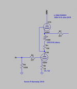
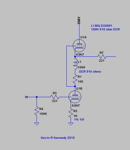
Another variant that I like subs a 6SN7 with a choke and series resistor in place of the cathode resistor in the upper tube of the SRPP. I dubbed this a choke augmented mu follower when I first thought of it 20yrs ago. (I suspect lots of others came up with this as well.) Direct coupling to the grid of the 2A3 in this case. See attachment for what I am talking about. Gain is mu, and the Vs can range from 300 - 400V as suits the output stage. DC on the output cathode is very close to 1/2Vs. I run this at 8 - 10mA, it can comfortably swing > 100Vpp. (At 400V it will drive a 300B to 180Vpp) There may be benefit to bypassing R2 with a good quality electrolytic if you need a lot of swing. (I usually don't)
Note the loktal equivalent of the 6SN7 is the 7N7, which is generally a great choice unless you need to run it at much over 300V on the upper plate in which case it is a very questionable choice IMLE.
I have no idea what RL experience means, but I have designed dozens of tube amplifiers over the past few decades if that helps.
Attachments
I used a 6SL7 based SRPP in my earliest SE 45 design at about 2mA of plate current, Vs to the SRPP was 320V, and it worked quite well actually.
Another variant that I like subs a 6SN7 with a choke and series resistor in place of the cathode resistor in the upper tube of the SRPP. I dubbed this a choke augmented mu follower when I first thought of it 20yrs ago. (I suspect lots of others came up with this as well.) Direct coupling to the grid of the 2A3 in this case. See attachment for what I am talking about. Gain is mu, and the Vs can range from 300 - 400V as suits the output stage. DC on the output cathode is very close to 1/2Vs. I run this at 8 - 10mA, it can comfortably swing > 100Vpp. (At 400V it will drive a 300B to 180Vpp) There may be benefit to bypassing R2 with a good quality electrolytic if you need a lot of swing. (I usually don't)
Note the loktal equivalent of the 6SN7 is the 7N7, which is generally a great choice unless you need to run it at much over 300V on the upper plate in which case it is a very questionable choice IMLE.
I have no idea what RL experience means, but I have designed dozens of tube amplifiers over the past few decades if that helps.
Does push pull action of the SRPP compensate for frequency dependent behavior (if any) of the choke? Will output impedance rise compared to a 1K resistor?
Hi there,
I am planning to build a 2A3 SET amp, and have been comparing various circuits. Currently, the available choices have burned down to the following three...
Two things to consider
a) loftin white - you can get rid of one capacitor (at the cost of no A2)
b) You can't get linearity back once lost - so driver tube inherent linearity is the be all and end all. (See Lynn's article)
I presume you read the SP 15 article on 2A3s?
Thx for your replies,
@Eli
The MOSFET power drive is no longer direct coupled, and I consider it as a hybrid amp, although I have to admit, apparently it combines the best of both worlds.
@kevinkr
The choke augmented srpp looks nice so I went ahead and made some spice simulations. Besides the advantages you mentioned, unfortunately I also found some drawbacks (if spice is correct).. the choke introduces higher order harmonics and rolls of the bass response..
This is with a 6SL7. With a 6SN7, the effects are less noticeable, but the gain is too little to direct couple the 2A3. Unless you go for higher Vs, but then you need to raise all voltages on the 2A3 to insane levels..
The choke augmented setup seems nice overall, but it doesn't seem to fit for my application.
How does that apply to each of the 3 circuits I introduced in post #1?Two things to consider
a) loftin white - you can get rid of one capacitor (at the cost of no A2)
Great reading, thx.b) You can't get linearity back once lost - so driver tube inherent linearity is the be all and end all. (See Lynn's article)
@Eli
The MOSFET power drive is no longer direct coupled, and I consider it as a hybrid amp, although I have to admit, apparently it combines the best of both worlds.
Hybrid, shmybrid. Who cares! The object of the exercise is superior reproduction of recorded music. That, IME/IMO, means tubes do most of the heavy lifting. However, FETs make terrific "spear carriers" for tubes. Like tubes, FETs are high impedance, voltage controlled, devices. Think heaterless pentode.
A favorite part of mine is the IRFBC20. It exhibits low and stable reverse transfer capacitance, which is crucial to linearity in voltage follower (current amplifier) service. Show me something "hollow state" that can yield a transconductance in the (sic) hundreds of mA./V. 
I'm very dubious about FET voltage amplifiers. As current amplifers, FETs kick @ss!
<snip>
This is with a 6SL7. With a 6SN7, the effects are less noticeable, but the gain is too little to direct couple the 2A3. Unless you go for higher Vs, but then you need to raise all voltages on the 2A3 to insane levels..
<snip>
Yes, the circuit is intended for use with the 6SN7 and is not very practical with the 6SL7 which has about 10X higher RP.
I actually have built a number of 2A3 based amplifiers using this circuit direct coupled to 2A3, and 1.5Vrms is sufficient to drive it to full output so I am assuming you need much higher sensitivity than this?
Lundahl makes a 270H henry choke that I suspect would provide better results than the 100H chokes I used.
It's just one of a number of options to experiment with which is why I posted it.
@ Disco: The circuit I posted actually is not pushpull and not an SRPP at all, but a variant on the mu-follower and performs similarly within the limits of the choke's inductance and inter-winding and capacitance to core. It has a small advantage over the standard mu-follower wrt supply voltage requirements as the voltage drop across the choke is generally much smaller than that of the bias and load resistor in the conventional mu-follower.
Speaking of direct coupled circuit, there was a schematic published in Sound Practices in 1993 by Wavelength Audio that uses a 6BM8's triode to drive a 45 triode. The pentode of 6BM8 is acting as constant source for the 45's cathode. It should not be too hard to tweak it to work for 2A3. If octal is preferred, a 6EM7 can replace the 6BM8, I believe. Or if you insist on 6SL7 then, you have to add another tube like 6BQ5, 6V6, 6L6 or triodes like 6AH4, 6CK4, 6BX7, 6BL7 etc.... for the output tube's cathode. Have fun!
Non-resistively loaded "totem pole" setups are interesting.
Australian DIYers have done considerable work on choke loaded SRPP. Inductive reactance at 20 Hz. should be 3X RP, which is problematic for types like the 6SL7.
Morgan Jones' beta follower, which employs a BJT as the load, is another setup worth investigating. Perhaps careful selection of the BJT would make this variant a good choice in combination with the 6SL7.
So maybe I didn't look close enough and gave up too early with the simulations. I guess what put me off for my project was the high cost of big chokes..I actually have built a number of 2A3 based amplifiers using this circuit direct coupled to 2A3, and 1.5Vrms is sufficient to drive it to full output so I am assuming you need much higher sensitivity than this?
Lundahl makes a 270H henry choke that I suspect would provide better results than the 100H chokes I used.
Anyways, I'll keep your suggestion in the drawer of noteworthy designs.. Thanks!
Thru the bootstrap cap, the cathode follower acts as a quasi ccs for the initial input stage, boosting its gain to almost µ. The cathode resistor bypass cap of the input stage can be dropped. Also, the input stage work in a more more linear regime.why is the "cap bootstrap" required for the cathode follower version?
The choke does not have to be particularly large at all.
Imo, it doesn't need to be anything special, it just has to be an inductor of sufficient inductance and power handling. The power handling is on the order of a watt or two... afaik it could be the primary or secondary of a suitable power xfmr. Ought to be very low cost.
Goldenbeer, it acts as a quasi CCS for the input stage?
Don't exactly see that.
But it is a cap - and couples more at HF than low...
...I'll have to take ur word for it, lacking the time or fortitude to do a simulation myself.
_-_-
How does that apply to each of the 3 circuits I introduced in post #1?
Your middle circuit appears direct coupled and thus I presume you've seen all the Loftin White variants and discarded them. Or not - it still remains an interesting way to avoid a coupling capacitor.
The circuit I posted actually is not pushpull and not an SRPP at all, but a variant on the mu-follower and performs similarly within the limits of the choke's inductance and inter-winding and capacitance to core. It has a small advantage over the standard mu-follower wrt supply voltage requirements as the voltage drop across the choke is generally much smaller than that of the bias and load resistor in the conventional mu-follower.
Non-resistively loaded "totem pole" setups are interesting. Australian DIYers have done considerable work on choke loaded SRPP. Inductive reactance at 20 Hz. should be 3X RP, which is problematic for types like the 6SL7.
So, the circuit is in single ended operation with the upper valve acting as a constant-current source? That would make a voltage amplifier with maximum peak current flow equal to the quiescent current. However, there's the choke with its energy stored in the magnetic field. Can it deliver the juice a DHT asks for driving Miller capacitance? How's linearity at that point? DC resistance should be low in that case...
Last edited:
Your middle circuit appears direct coupled and thus I presume you've seen all the Loftin White variants and discarded them. Or not - it still remains an interesting way to avoid a coupling capacitor.
I would say all three circuits are direct coupled, in the sense that the output of the previous stage couples directly to the input of the next one.
The cathode follower couples its output to the anode of the input stage by means of a cap. You could call this cap as being in the signal path or not. You could also call this some kind of feedback.
I am not sure if it thins the sound, and I never heard of any first hand experience with this topology.
Don't know of I've seen all the Loftin White variants, but if there's any other, I am pleased to have it pointed out.
So, the circuit is in single ended operation with the upper valve acting as a constant-current source? That would make a voltage amplifier with maximum peak current flow equal to the quiescent current. However, there's the choke with its energy stored in the magnetic field. Can it deliver the juice a DHT asks for driving Miller capacitance? How's linearity at that point? DC resistance should be low in that case...
Operation is very analogous in most ways to a standard mu follower, however fairly high current operation is possible - I run these at around 10mA with a 6SN7 and output z should be < 500 ohms. The upper tube acts as both a cathode follower and current source, appropriately chosen the choke provides a large reactance that loads the lower tube and is bootstrapped by the follower on top. The quality and value of the inductor does matter as large amounts of capacitance to core or adjoining windings will result in HF roll off. Using a good choke - 3dB points of <20Hz and > 60kHz can be achieved.
It is quite practical to use similar tubes in this circuit with a higher transconductance triode running at higher current on the top - to do this all that is required is to add an appropriately sized resistor (or current source) between the cathode of the upper tube and ground.
- Status
- This old topic is closed. If you want to reopen this topic, contact a moderator using the "Report Post" button.
- Home
- Amplifiers
- Tubes / Valves
- 3 direct coupled 2A3 amps