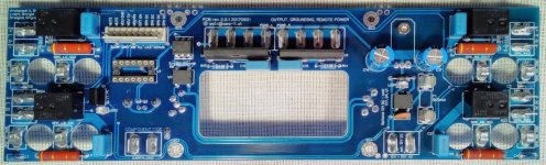
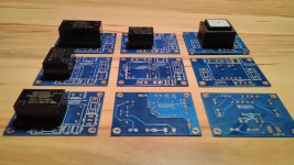
Great!... assembled ...
Better pictures will follow ...
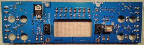
I see you prefer the fast on connector solution.
Maybe i will follow in the same way.

This is very good. Can you send me an electric circuit, program and software? Thank you! Mailbox 75009459@qq.comSome parts are missing and MOSFETs have to be matched for the 200W CFA and also for my new 50W MOSFET VFA.Attached some pictures from my "mass transistor matcher" prototype in action.... more in ~ 1 or 2 weeks ...
This is a project which may never be finished. Microcontroller software and PC software isn't distributable. Additionally you need 3 dedicated DVM meters with galvanically isolated USB interfaces to read the current/voltages.
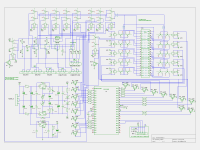
The circuit is nothing special - many relays controlled by pic micro and a piece of PC software (perl script running under linux) which calculates the results from values read via the DVM meters.
Note: this circuit has some errors. Better not to use it.
The circuit is nothing special - many relays controlled by pic micro and a piece of PC software (perl script running under linux) which calculates the results from values read via the DVM meters.
Note: this circuit has some errors. Better not to use it.
Attachments
Last edited:
Hi Toni,can you post a simple measurement circuit(one or two pieces of fet each time) ?This is a project which may never be finished. Microcontroller software and PC software isn't distributable. Additionally you need 3 dedicated DVM meters with galvanically isolated USB interfaces to read the current/voltages.
The circuit is nothing special - many relays controlled by pic micro and a piece of PC software (perl script running under linux) which calculates the results from values read via the DVM meters.
Note: this circuit has some errors. Better not to use it.
I am an electronic lover, not a businessman.This is a project which may never be finished. Microcontroller software and PC software isn't distributable. Additionally you need 3 dedicated DVM meters with galvanically isolated USB interfaces to read the current/voltages.
The circuit is nothing special - many relays controlled by pic micro and a piece of PC software (perl script running under linux) which calculates the results from values read via the DVM meters.
Note: this circuit has some errors. Better not to use it.
Hi Toni,can you post a simple measurement circuit(one or two pieces of fet each time) ?
Should help - take some cheap parts and do some experiments.
You need up to 2 DVM during measurements. The 10V supply should be very stable!
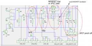
hFE measurement needs calculation:
hFE = Ic/Ib
Pseudocode:
MOSFET or JFET measurements:Pseudocode:
Ib=Vhfe1 / R3
Ic=Vhfe2 / R4
hFE=Ic / Ib
Ic=Vhfe2 / R4
hFE=Ic / Ib
R7 or R8 connected to drain is to measure Vgs for low or high DS currents. Depends on the parts you want to measure.
Google search will help you too ...
BR, Toni
Attachments
Last edited:
JFET MOSFET doesn't understand. Can you send me a detailed explanation?Should help - take some cheap parts and do some experiments.
You need up to 2 DVM during measurements. The 10V supply should be very stable!
hFE measurement needs calculation:hFE = Ic/IbMOSFET or JFET measurements:
Pseudocode:
Ib=Vhfe1 / R3
Ic=Vhfe2 / R4
hFE=Ic / Ib
R7 or R8 connected to drain is to measure Vgs for low or high DS currents. Depends on the parts you want to measure.Google search will help you too ...
BR, Toni
JFET MOSFET doesn't understand. Can you send me a detailed explanation?
For more details read the MOSFET matching article on PASS homepage
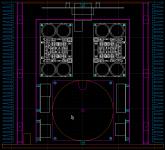
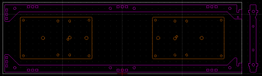
I see two options.... helper power supply pcb for backplane or other needs ...
BR Toni,
1)using a transformer
2)using an a.c to d.c converter.
yes - correct! The transformer solution is reliable and cheap and the preferred solution to power the backplane.
The SMPS solution is a bit more expensive but can be used for microcontroller projects too where extremely low power is needed to fulfil EU needs for standby powered devices. The shown pcb allows to use RECOM RAC02, RAC03, RAC04 or RAC10 series.
I will try both variants during measurements to test for added noise levels...
Last edited:
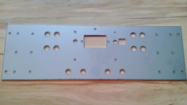
SA2015 4 channel VMOS - case layout
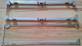
- lasered stainless steel backpanel. First part of the backpanel "sandwich". (3mm thick backpanel is constructed using 1.5mm thick stainless steel and 1.5mm engraved aluminium; this allows to hide many of the needed M3 screws).
- heatsink, top, bottom mounting helpers. lasered from stainless steel 2mm. Frontpanel mounting helper on left side. Front panel can be inserted from top and fixed using a M3 screw. Easy and fast removeable for maintenance.
Attachments
Last edited:
Is this a diy procedure?
- lasered stainless steel backpanel. First part of the backpanel "sandwich". (3mm thick backpanel is constructed using 1.5mm thick stainless steel and 1.5mm engraved aluminium; this allows to hide many of the needed M3 screws).
Have fun, Toni
- heatsink, top, bottom mounting helpers. lasered from stainless steel 2mm. Frontpanel mounting helper on left side. Front panel can be inserted from top and fixed using a M3 screw. Easy and fast removeable for maintenance.
- Home
- Amplifiers
- Solid State
- 2stageEF high performance class AB power amp / 200W8R / 400W4R