@ DJK.
Yes, I have, MJ15015 are very good.
Problem is, I sweep clean the Importer´s stock and maybe they don´t get more for months.
It´s not a "famous" transistor so it´s not on their priority list.
They offer me MJ15003 and such ..... fake!
In my higher power amps (+/-70V rails) I was lucky with MOSPEC 2N3773 .... until they also started showing up falsified.
Fact is, famous/popular ones are high on the faker´s list.
Do not even try to buy Toshibas !!!
@ KenPeter : Make a test jig: 3 crocodile clips, a 100 ohm Base to Emitter resistor , a 10K or 4K7 10W rsistor in series with the collector an an around 300VDC power supply.
Negative to Emitter, Positive to collector through the 10W resistor, 100 ohms base to emitter.
You measure voltage drop Collector to Emitter.
Don´t delay more than 10 to 20 seconds, you are stressing it, it´s ample time anyway.
Disconnect it and write voltage with Sharpie on transistor case.
You are measuring Vcer(sust) which means: voltage, collector to emitter, with a 100 ohm resistor base to emitter, "sustaining" , which would be *similar* to "Zener voltage".
It´s not the same, just an analogy.
It tells you at what voltage the transistor will die (because in real life you will not have a limiting resistor in series) so use *at least* 10 to 20V higher transistors than your maximum rail to rail voltages under any condition.
On the practical side: in "the old days"competition was based on quality ("buy mine because it´s better than others"), so it was normal to find up to 120V 2N3055.
Motorolas could be twice the price of others and still sell well. And RCAs were mythical.
Today, competition is cutthroat based on price, so even "good" ones such as Motorolas and ST, meet but not surpass rated specs.
You´ll find 80V devices, with the odd 90V ... no more.
An exception, which should be taken with a grain of salt.
"Fresh" so called Toshiba 2N3055, are fake, yet quite well made, often stand up to 120V , have good Beta, etc.
Problem is, the copper "coin" to which is soldered the actual square chip inside the steel case is smaller than needed , so they don´t dissipate heat well.
I trust them for 40 to 60W Hi Fi home amplifiers, not more.
Not reliable enough for often abused guitar amps.
@ DJK.
Today, competition is cutthroat based on price, so even "good" ones such as Motorolas and ST, meet but not surpass rated specs.
You´ll find 80V devices, with the odd 90V ... no more.
An exception, which should be taken with a grain of salt.
"Fresh" so called Toshiba 2N3055, are fake, yet quite well made, often stand up to 120V , have good Beta, etc.
Problem is, the copper "coin" to which is soldered the actual square chip inside the steel case is smaller than needed , so they don´t dissipate heat well.
I trust them for 40 to 60W Hi Fi home amplifiers, not more.
Not reliable enough for often abused guitar amps.
Interesting observations. You have a lot of experience and knowledge arround this.
Concerning internal disspiate heat problems I had observe the same effect by Toshiba's 2SA1943/2SC5200 in a Class-A Luxman L550 - read post #22 about
http://www.diyaudio.com/forums/solid-state/190160-fake-components-3.html
What about the quality and realibility of this semiconductor brand:
:: Welcome :: MOSPEC SEMICONDUCTOR:
 OWER TRANSISTORS
From nice sounding UK Armstrong vintage Receiver series 600 amplifier schematic part :
40636=2N3055 , from RCA Solid State Power Transistor Directory 1976 :
40636 datasheet and application note, data sheet, circuit, pdf, cross reference, pinout | Datasheet Archive
40636=2N3055 , from RCA Solid State Power Transistor Directory 1976 :
40636 datasheet and application note, data sheet, circuit, pdf, cross reference, pinout | Datasheet Archive
Attachments
MOSPEC are very good .... but I have also been offered fakes.
Be careful picking a supplier.
I use their excellent 2N3773, a "forgotten" workhorse, but lately I only find the worst fakes, the ones that *do not even have the heat distribution copper coin*, the (admittedly quite large) chip is soldered straight to the steel base.
Easy to spot, because it´s almost 1/8" thick, in an useless attempt to make it spread heat somewhat.
I have been offered also "MJ15003/4" in the same gross case.
Silkscreen is so cheap!!
In this video you can see 3 of my 300W Bass amps, each with +/-70V rails, driving a 4 ohm 8x10" Ampeg cabinet.
Each uses 4 x 2N3773, driven by MJ15030 and 15031
*Everything* is fan cooled, even the drivers , and more important, the power transformer .
(it´s always forgotten, yet it suffers a lot when the heads work hard 5 to 8 hours in a row, such as in a Rock Festival)
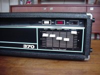
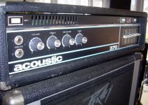
My heads are the ones clearly visible at the right of the bass player/singer´s head, the ones with white front panels and an oversized Red Led=
Almafuerte - YouTube
The Fake situation got so bad, that now I only use IRFP250.
Any brand, usually IR, ST or Fairchild.
Cheap, abbundant, unglamorous, are not worth faking.
Yes, the sound is clearly brittle, "rougher", compared to bipolars.
Yet the much increased reliability more than forgives that.
MosFets have no Second Breakdown !!
Be careful picking a supplier.
I use their excellent 2N3773, a "forgotten" workhorse, but lately I only find the worst fakes, the ones that *do not even have the heat distribution copper coin*, the (admittedly quite large) chip is soldered straight to the steel base.
Easy to spot, because it´s almost 1/8" thick, in an useless attempt to make it spread heat somewhat.
I have been offered also "MJ15003/4" in the same gross case.
Silkscreen is so cheap!!
In this video you can see 3 of my 300W Bass amps, each with +/-70V rails, driving a 4 ohm 8x10" Ampeg cabinet.
Each uses 4 x 2N3773, driven by MJ15030 and 15031
*Everything* is fan cooled, even the drivers , and more important, the power transformer .
(it´s always forgotten, yet it suffers a lot when the heads work hard 5 to 8 hours in a row, such as in a Rock Festival)
My heads are the ones clearly visible at the right of the bass player/singer´s head, the ones with white front panels and an oversized Red Led=
Almafuerte - YouTube
The Fake situation got so bad, that now I only use IRFP250.
Any brand, usually IR, ST or Fairchild.
Cheap, abbundant, unglamorous, are not worth faking.
Yes, the sound is clearly brittle, "rougher", compared to bipolars.
Yet the much increased reliability more than forgives that.
MosFets have no Second Breakdown !!
I've got an RCA output transistor removed from a blown up dynakit ST120 in about 1985. The number 574844 C F 2K. Since the 2n3055 had 60v Vce, and the upper rail voltage was 80V, these were probably selected from the process for Dynaco by RCA. They operate at 1/2 rail after the capacitor charges up, but gets the whole voltage at turn-on. The silicon die is 5.5mm square. The copper coin is about 11 mm square with the corners cut off to fit inside the can circle. I knew I would learn something someday by sawing the top off this and leaving it in the transistor bin.I didn't know about the copper until I scratched it. Thanks for the discussion. Thanks for the tip on fake detection. Buying from Newark, I'm not too worried.
Pity about the fake supply in your country. I can get MJ15015 by the hundred here, and they are made in Mexico. Shouldn't be so hard to drive them down the Pan American highway. Newark(farnell owned) had a big sale last year on MJ15015,I bought 24 or so before I discovered the MJ21195-6 courtesy Peavey. SOA wasn't the problem on the ST120 anyway, the last time I blew it up the trigger event was the melting of the solder on the output capacitor (no holes in the snap-on leads). At the end of a 3.5 hour Christmas cantata rehearsal. Stays cooler with fans on the heatsink now. Listening to it today, all day.
Pity about the fake supply in your country. I can get MJ15015 by the hundred here, and they are made in Mexico. Shouldn't be so hard to drive them down the Pan American highway. Newark(farnell owned) had a big sale last year on MJ15015,I bought 24 or so before I discovered the MJ21195-6 courtesy Peavey. SOA wasn't the problem on the ST120 anyway, the last time I blew it up the trigger event was the melting of the solder on the output capacitor (no holes in the snap-on leads). At the end of a 3.5 hour Christmas cantata rehearsal. Stays cooler with fans on the heatsink now. Listening to it today, all day.
Last edited:
in a lot of guitar amps i repaired in the 80's and 90's i used MJ15024s in place of 2N3055s quite often. only had a problem with a rebuild of one amp (only to find out later, that particular model, the Acoustic 370, had a reputation of not being repairable after an output stage failure). the wider SOA and better beta stability make the MJ15024 a good choice for a rebuild of a 2N3055 amp. ON is still making the MJ15024 (and it's complement, the MJ15025) in huge quantities.
What about the MJ21194?in a lot of guitar amps i repaired in the 80's and 90's i used MJ15024s in place of 2N3055s quite often. only had a problem with a rebuild of one amp (only to find out later, that particular model, the Acoustic 370, had a reputation of not being repairable after an output stage failure). the wider SOA and better beta stability make the MJ15024 a good choice for a rebuild of a 2N3055 amp. ON is still making the MJ15024 (and it's complement, the MJ15025) in huge quantities.
By compare the datasheets of this type and that one from MJ15024 I have found no significant differences; OTOH - not all diagrams are directly comparable.
http://www.onsemi.com/pub_link/Collateral/MJ15022-D.PDF
http://www.onsemi.com/pub_link/Collateral/MJ21193-D.PDF
Getting significantly higher SOA for a couple extra dollars is good business in my book.
Anyway in servicing, bench time costs much more than parts needed (we are talking SS here and, obviously excluding, say, a burnt power transformer) so you can go for the best with no penalty.
I had to switch because in production, a couple dollars mean a lot after the product runs along all the marketing chain and reaches the final customer.
As of the Acoustics, the designer liked challenges (let´s put it mildly) and used *no* emitter ballast resistors to even out current among (very hot) output transistors, biased them "hot" (literally) *and* bolted them to the *bottom* of the chassis, no fins or fans or ventilation slots involved.
Not exactly the best heat dissipation system either (Ilm also putting it mildly).
Yes, at least he cut a "window" in the cabinet´s bottom wood.
They had all that free space between head and cabinet to cool themselves.
I´m sure he got his transistors tightly matched, not only in Hfe/Beta but even more importantly, in Vbe at different temperatures.
Possible, if you buy in bulk house numbered parts straight from Motorola or whatever, a PITA for a serviceman who buys a few from a regular shop.
I routinely added 0.33 ohm 5W emitter resistors , just "floating" in the air like a Modern Art sculpture.
Last edited:
"Getting significantly higher SOA for a couple extra dollars is good business in my book."
Sure, but the big amps using a 2N3055 probably ran at no higher than ±40V or so, and might have delivered 100W/4Ω if you looked at the watt-meter cross-eyed. Most of those 100W rated amps had two pair of outputs, or 720W SOA if we replaced them with MJ15015 vs the 460W SOA with the original 2N3055. With the typical mark-up on parts, and the cost back then, the difference in the repair bill would have been at least $20, trivial today? Not so 20~25 years ago.
Sure, but the big amps using a 2N3055 probably ran at no higher than ±40V or so, and might have delivered 100W/4Ω if you looked at the watt-meter cross-eyed. Most of those 100W rated amps had two pair of outputs, or 720W SOA if we replaced them with MJ15015 vs the 460W SOA with the original 2N3055. With the typical mark-up on parts, and the cost back then, the difference in the repair bill would have been at least $20, trivial today? Not so 20~25 years ago.
actually the MJ21194 and similar Toshiba process devices do have one very significant difference. the beta is very stable up to about 10A compared to the MJ15024. this makes for a much more linear transistor. of course the difference might not be as big in a quasi-complementary amp if you look at the output stage linearity curves in Doug Self's book.
as to the Acoustic 370 problems, i never did get that beast working. i tried 3 times rebuilding it from input to output, replacing all the silicon and burnt resistors. i'd bring it up slow on a variac, and as soon as i got to 60V BZZZT!!!!! up in smoke it went.... i later found other techs had the exact same experience with 370's and wouldn't touch them. 20 years later i have offered to rebuild my friend's amp again, this time using a different design amp circuit. (fully complementary with MJL4281/4302 outputs)
as to the Acoustic 370 problems, i never did get that beast working. i tried 3 times rebuilding it from input to output, replacing all the silicon and burnt resistors. i'd bring it up slow on a variac, and as soon as i got to 60V BZZZT!!!!! up in smoke it went.... i later found other techs had the exact same experience with 370's and wouldn't touch them. 20 years later i have offered to rebuild my friend's amp again, this time using a different design amp circuit. (fully complementary with MJL4281/4302 outputs)
Which SOA you mean?"no significant differences; "
Other than the 100W @100V vs 200W @100V SOA they are quite similar.
The newer parts use the perforated emitter technology they got from Toshiba.
One SOA shows the boundary line (threshold line) for only one second (MJ21194) and the other the "BONDING WIRE LIMITED" line (MJ15024).
The mentioned lines inside of the diagram by MJ15024 - "THERMAL LIMITATION" (SINGLE PULSE) so as "SECOND BREAKDOWN LIMITED" I don't see in the diagram (perhaps the colored lines are not to see in this pdf datasheet).
Thus I cannot compare this SOA diagrams.
The line for DC conditions I don't find by both data sheets.
What important detail from onsemi, revealing the necessary information, I have overlooked ??
In this case I have start for several months this thread:
http://www.diyaudio.com/forums/soli...93-21194-no-data-soa-during-dc-conditios.html
without really helpful informations.
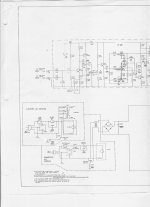
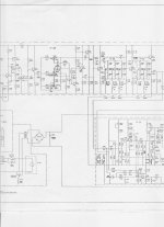
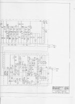
In the attachments schematic jpg's with higher resolution.
By this output buffer topology and the kind of parallel operating mode without emitter resistors (and only 1 ohms for the second buffer stage transistor), for me it is a miracle which great reliability with the original components was achieved. By repair I remove the first stage of the buffer (darlingron is enough) and switched parallel only three darlingtons (resp. sziklai darlingtons in the lower half).as to the Acoustic 370 problems, i never did get that beast working. i tried 3 times rebuilding it from input to output, replacing all the silicon and burnt resistors. i'd bring it up slow on a variac, and as soon as i got to 60V BZZZT!!!!! up in smoke it went.... i later found other techs had the exact same experience with 370's and wouldn't touch them. 20 years later i have offered to rebuild my friend's amp again, this time using a different design amp circuit. (fully complementary with MJL4281/4302 outputs)
Attachments
Last edited:
another thing i'm thinking here is that with non-factory selected devices, the miller capacitance is different, and the repaired amp is oscillating for the few milliseconds it takes for the amp to self destruct. since this IS a bass amp, maybe starting with a 1nf cap across C308, (overcompensated is better than undercompensated) and experimentally working down from there might stabilize the amp for the newer devices. current limiting the supply to the drivers and output devices with resistors may also be wise on the first power-up (as well as using a dim-bulb limiter after the variac, which i didn't know about 20yrs ago).... just a few thoughts.....
At first, I found the MC2100's choice of emitter resistors confusing.
It seemed to me a deliberate unbalance at max current. And it is!
But not so much as might seem, if the outboard pair are droopy,
and that droop starts about 3A (sound familiar?).
It seems they are all matched to the same collector current at the
point of greatest challenge to SOAR. The halfway point of voltage
and current. Not at max current as I had first assumed. But droop
might be required to maintain current balance beyond halfway.
The inboard transistor will not exceed 3.75A + drive.
The outboard transistors will not exceed 4.2A apiece.
A Darlington watching the last emitter cuts off bias if it trys.
I calculate 35V-5Edrops=31.5 into 2 ohm tap =15.5Amps,
but the emitter watcher will cut us off at 12.6A, assuming
all three are still in balance.
I don't see any particular reason (beyond VCE) 2n3055 shouldn't
work here? If the outboard pair droop a bit, it only helps collector
balance. But I see no advantage for the first of this trio to droop,
only makes the small transistors on the driver board work harder.
So maybe one modern non-droopy type, and a matched pair of
good old 2n3055 on the cheap... If we can prove they are 80V.
The one with the insulator is probably the last quasi, as it has
0R33 in the collector to watch current there (don't go looking,
its slightly below where my image crops) . I've seen videos of
MC2100 repair misidentify that transistor as the driver...
Attachments
Last edited:
If the 12.2A cutoff (into 2R) is believeable. There won't be enough voltage
swing at the 2 ohm tap to exceed 60VCE. I think maybe this is trusting the
load and OPtransformer a bit much... I still think I need at least 80V parts.
The rails can be a few volts higher than 35V when nothing is happening.
swing at the 2 ohm tap to exceed 60VCE. I think maybe this is trusting the
load and OPtransformer a bit much... I still think I need at least 80V parts.
The rails can be a few volts higher than 35V when nothing is happening.
Last edited:
40411 = selected 2N3055 ??
I used to fix a lot of consumer electronics and MI amplifiers back in the early 70'a. I made a few big amps too. Whenever I had dead power transistors I usually cut the tops off with a bench grinder to see what was inside. The 40411 had a larger die than any RCA branded 2N3055. I believe it had a higher breakdown voltage rating.
I was always searching for the best transistors to use in the guitar amps that I built. I got a big box of military surplus RCA "2N3055" transistors with the RCA logo and the house number 39414. The die looked the same as a RCA 2N3055. I used the old transformer driven totem pole circuit running 6 transistors from a 110 volt rail. They could crank out 250 watts into a 4 ohm load for ever without blowing up.
Later I found out that Solitron was making transistors for NASA in a plant in Riviera Beach Florida, so I did some dumpster diving and got some really big transistors in strange packages with two very large die inside. There were some TO3 packages with one of the same die. These guys could handle 120 volts C-E at 1 amp, and 20 amps at 5 volts, but they blew up when I played guitar thriugh them.
I was rummaging through a military surplus salvage yard when I found a large power converter. It takes in 3 phase 60 Hz power and generates 3 phase 400Hz power. It had several round heat sinks with a muffin fan on each end. There were 24 X Westinghouse 2N3773's wired in 4 banks of 6 each with their own emitter resistor. I wired one of these things as a totem pole with 2 banks of 12 running from rectified 120 volts (about 155 VDC) My instructions to the band was....plug in as many speakers as you want. THe more you plug in, the louder it gets. We believe there were about 1200 watts with a 2 ohm load, but no one ever really measured it. This thing tripped the line breaker a few times but never blew up. I made it in 1970, I replaced the electrolytics in about 1988, haven't seen it since.
"I've seen videos of MC2100 repair misidentify that transistor as the driver... "
It is (what I would call) a driver transistor, biased class AB. The outputs are class B. The driver transistor will deliver about 1A before the outputs go into conduction.
The MC2300 is the same with 0R68 emitter resistors on the drivers (four drivers and eight outputs).
It is (what I would call) a driver transistor, biased class AB. The outputs are class B. The driver transistor will deliver about 1A before the outputs go into conduction.
The MC2300 is the same with 0R68 emitter resistors on the drivers (four drivers and eight outputs).
- Home
- Amplifiers
- Solid State
- 2N3055 inside - commercial famous amplifier models, quasi complementary power output