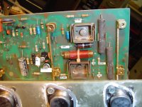
Thanks for the schematic. Several years ago I had the Acoustic 370 or model 371 (same amp but in combination with 301 bass cabinet) for repair. Like by several other amps with triplet quasi-complementary super ß buffer in the output also here was unwanted oscillation the main problem - read more from post #20 aboutlet's not forget the Acoustic Controls 370 bass amp..... the "house numbered" transistors are actually 3055s. only one problem with this amp... if the outputs blew the amp was done. no amount of rebuilding would fix it.
http://www.diyaudio.com/forums/solid-state/113943-quad-303-triple-cascade-2.html
In this case, I had made short work: I reduced the upper half to a normal darlington topology and the lower half to a Sziklai Darlington. The amplifier is running fine since performing this steps.
The challenge to achieve stable operation with a super beta push pull quasi complementary follower was too large (because too expensive) for me.
Several pics (unfortunately not from my own repair work) you will find in the attachements and about
BassHead370 < Acoustic < Wiki
BassCabinet301 < Acoustic < Wiki
Acoustic 370 Repair
??????[acoustic 370]?????????? - ROCK???????
BTW - amps in that kind are perfectly suited for evaluation applications, because there is present space enough.
Attachments
-
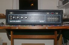 Acoustic 370 (371) front.jpg98.5 KB · Views: 1,316
 -
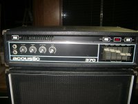 Acoustic 370+301 front.jpg111.3 KB · Views: 1,271
 -
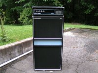 Acoustic 370+301 front-II.jpg90.3 KB · Views: 1,232
 -
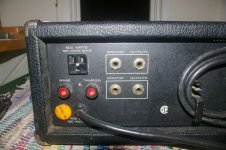 Acoustic 370 terminal aera.JPG123.2 KB · Views: 131
 -
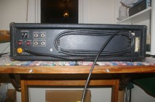 Acoustic 370 rear side.JPG106.8 KB · Views: 1,183
 -
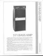 Acoustic Control Model 371 short form.jpg80.4 KB · Views: 1,237
 -
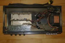 Acoustic 370 PCB top view.JPG106.6 KB · Views: 227
 -
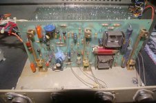 Acoustic 370 Power Amp PCB.JPG117.1 KB · Views: 298
 -
 Acoustic 370 Power Amp PCB Hres.JPG408.8 KB · Views: 376
 -
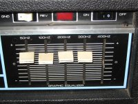 Acoustic 370 Equalizer aera.jpg645.8 KB · Views: 330
Last edited:
i rebuilt one of these beasts for a friend..... 3 TIMES!!!! and each time, i'd be bringing it up slow on a variac, and when i got to 60 volts WHAM!, the ammeter needle would peg, and bye-bye to another whole set of parts..... i thought i was making some kind of mistake, until i talked to other amp techs, and found they had all the same experiences. glad to know there's a cure for it. i didn't have a schematic available at the time. i had to build my own by following wires and traces. one of the things that did seem odd to me at the time were the output devices being paralleled with no separate emitter resistors. bipolars hog current, and this alone is it's own set of accidents waiting to happen.... i've offered to rebuild my friend's amp (after about 20 years of it being a 65lb preamp) with a fully complementary design, that's a whole lot more stable and MJL4281/4302 output devices, which are a whole lot "beefier" and much more linear. of course it won't have the same "quasi" sound, and won't behave badly when clipped (which isn't so bad since there's no tweeters to fry). with it being a bass amp i can probably get away with OVERcompensating it.
Last edited:
I am still hope for getting this schematicI need a schematic of follow integrated amp with quasi complementary output stage (2x2N3055/ch) and high pass couple capacitor (4.700uF/25V WIMA) between buffer out and speaker terminal:
Model No "V716" (V 716)
the manufacturer was Südfunk-Apparatebau Dr. Ing. Robert Ott
the device from me is branded with "Südfunk" (silver front panel)
the devices from the attached images are branded with "Universum" (special made for the German biggest mail order house at those days, - "QUELLE") That design was in black for the front panel.
Who can post a schematic ??

I've been told that 2N3055 is one of the worst transistors you could use for audio.
Now im confused.
You are right, but you are "Off-Topic". We don't talk about currently available versions (read post #1 !!! )
By amps e. g. mentioned by post #82-88 you cannot use currently available cheap versions for repair service.
Last edited:
in the MJ magazine between 1961 and 1968 there must to find such an advertisement.Who can post the first commercial advertisement (announcement) from formerly's brand RCA (from any electronic magazine published in the early sixties) concerning the 2N3055 and the first RCA application notes?
At which time was exactly launched the production?
http://www.diyaudio.com/forums/soli...early-index-1924-2009-wanted.html#post2094355
http://www.diyaudio.com/forums/everything-else/136060-why-i-buy-mj.html
also in the Electronics World from those days.
http://www.diyaudio.com/forums/soli...rrently-available-electr-audio-magazines.html
Last edited:
(series 20 NAD3020)
wasn't quasi, but yes, used Motorola's 2N3055 and the complementary, except one that i saw using Matsushita brand 2N3055..
Quite right. It used the 2N2955 along with the 2N3055.
Attachments
I always liked the input clip circuit that NAD used, they called it 'soft clipping'.
In reality it's a hard clip on the input signal with the clip point tracking the ± rails. It worked quite well and made clipping behavior a lot more stable because the feedback loop did not overload.
In reality it's a hard clip on the input signal with the clip point tracking the ± rails. It worked quite well and made clipping behavior a lot more stable because the feedback loop did not overload.
There are still various manufacturers of the 2N3055;
from which of the follow I can expect good quality and the same parameters than the old ones ?
Central Semiconductor :: Manufacturer of Discrete Semiconductors
:: Welcome :: MOSPEC SEMICONDUCTOR:OWER TRANSISTORS
Boca Semiconductor Corporation - Diodes, Transistors & Rectifiers
Manufacture Diodes, IGBTs, LED Driver, Small Signal & Analog, RF Power, SCR, WLAN Power Amplifier, Backlight Inverter, CCFL Inverter, Power Modules, RF Transistors, Power Over Ethernet, PoE, PoE IC
Farnell United Kingdom | world-leading distributor of electronic and maintenance, repair and operations products. (SPC/Multicomp)
TT electronics Semelab (rs components/Magnatec)
from which of the follow I can expect good quality and the same parameters than the old ones ?
Central Semiconductor :: Manufacturer of Discrete Semiconductors
:: Welcome :: MOSPEC SEMICONDUCTOR:
OWER TRANSISTORSBoca Semiconductor Corporation - Diodes, Transistors & Rectifiers
Manufacture Diodes, IGBTs, LED Driver, Small Signal & Analog, RF Power, SCR, WLAN Power Amplifier, Backlight Inverter, CCFL Inverter, Power Modules, RF Transistors, Power Over Ethernet, PoE, PoE IC
Farnell United Kingdom | world-leading distributor of electronic and maintenance, repair and operations products. (SPC/Multicomp)
TT electronics Semelab (rs components/Magnatec)
RCA- 35w CLASS AB AMP--application notes
Who can post the first commercial advertisement (announcement) from formerly's brand RCA (from any electronic magazine published in the early sixties) concerning the 2N3055 and the first RCA application notes?
At which time was exactly launched the production?
Well, I am sad to say I no longer have this peice of paper. I must have kept it for twenty-five years! Yes, it was the early sixties. sometime 1962 I suspect, that it came From RCA. I also have none of the amp!
I am happy to say I did build the amp, Though. It worked rather well, all through my college years. (after that I went to Germany). RCA 2n3055, of course. I used four rather too small heatsinks. Had a 2n2904 in a to-5 can, as well as the other driver. two diodes to be mounted on heatsink, and 200 ohms of trimpot to adj the bias.
No 44V transformer could be had, so I had to wind my own. 60V was specified on the data sheet. It was the spring of 1963, or Earlier? Seems when I was a frosh in college I did not have it, but by summer 1964 I remember the apt. that had the system (2AR-4 PAT4-AR turntable) set up. I cannot remember whether it had a two transistor input stage, or just one.
I had already built a PAS 3, which I noted would not drive this, as the input impedance of the amp was 10 K. Thus part of summer 1963 I put together the transistorized preamp. Somewhere in the files of RCA there would be an image of this, but for now we have to be happy that the topology was exactly like the various examples you have listed, from europe. DP
Who can post the first commercial advertisement (announcement) from formerly's brand RCA (from any electronic magazine published in the early sixties) concerning the 2N3055 and the first RCA application notes?
At which time was exactly launched the production?
Well, I am sad to say I no longer have this piece of paper. I must have kept it for twenty-five years! Yes, it was the early sixties. sometime 1962 I suspect, that it came From RCA. I also have none of the amp!
I am happy to say I did build the amp, Though. It worked rather well, all through my college years. (after that I went to Germany). RCA 2n3055, of course. I used four rather too small heatsinks. Had a 2n2904 in a to-5 can, as well as the other driver. two diodes to be mounted on heatsink, and 200 ohms of trimpot to adj the bias.
No 44V transformer could be had, so I had to wind my own. 60V was specified on the data sheet. It was the spring of 1963, or Earlier? Seems when I was a frosh in college I did not have it, but by summer 1964 I remember the apt. that had the system (2AR-4 PAT4-AR turntable) set up. I cannot remember whether it had a two transistor input stage, or just one.
I had already built a PAS 3, which I noted would not drive this, as the input impedance of the amp was 10 K. Thus part of summer 1963 I put together the transistorized preamp. Somewhere in the files of RCA there would be an image of this, but for now we have to be happy that the topology was exactly like the various examples you have listed, from europe. DP
If I know at least the exactly title of this paper I would be happy.
Last edited:
If I know at least the exactly title of this paper I would be happy.
Ask IEEE, JEDEC, etc:
IEEE Xplore - The 2N3055: a case history
Early sixties is for sure
Not long ago I bought an old Kirksaater receiver off Ebay. When I opened it up I found a whole passle of 3055/2955 pairs used for output devices. They used the MJ/MJE (TO-220) package, but basically the same complimentary pair. I've encountered their usage numerous times in commercial test equipment applications. I've used them myself on DIY amps I've built with very satisfying results, but have mostly migrated to D44VH10/D45VH10 as beefier options.
Doc
Doc
Ah, the good old IEEE - asking for money before you can read anything.
In this case the asking price is $30. In my part of the world that is not just small change.
Thanks for the link, though. It shows that the 2N3055 deserves a place in the electronics hall of fame.
40411 = selected 2N3055 ??
http://www.diyaudio.com/forums/solid-state/140988-vintage-brute-70-40411-clone.html#post2708633
http://www.diyaudio.com/forums/solid-state/140988-vintage-brute-70-40411-clone.html#post2708633
Who can post the first commercial advertisement (announcement) from formerly's brand RCA (from any electronic magazine published in the early sixties) concerning the 2N3055 and the first RCA application notes?
At which time was exactly launched the production?
Well, I am sad to say I no longer have this peice of paper. I must have kept it for twenty-five years! Yes, it was the early sixties. sometime 1962 I suspect, that it came From RCA. I also have none of the amp!
I am happy to say I did build the amp, Though. It worked rather well, all through my college years. (after that I went to Germany). RCA 2n3055, of course. I used four rather too small heatsinks. Had a 2n2904 in a to-5 can, as well as the other driver. two diodes to be mounted on heatsink, and 200 ohms of trimpot to adj the bias.
No 44V transformer could be had, so I had to wind my own. 60V was specified on the data sheet. It was the spring of 1963, or Earlier? Seems when I was a frosh in college I did not have it, but by summer 1964 I remember the apt. that had the system (2AR-4 PAT4-AR turntable) set up. I cannot remember whether it had a two transistor input stage, or just one.
I had already built a PAS 3, which I noted would not drive this, as the input impedance of the amp was 10 K. Thus part of summer 1963 I put together the transistorized preamp. Somewhere in the files of RCA there would be an image of this, but for now we have to be happy that the topology was exactly like the various examples you have listed, from europe. DP
In the meantime i have found about various sources this advanced history information:
1) The Signal Corps contract included Devices 13, 14, and 15 which subsequently evolved into the 2N1482, 2N1486, and 2N1490 families. The contract was completed with delivery of the required devices plus 8000 hour life test results with data entered (manually) onto data processing cards ( aka Hollerith or IBM cards). After several chip design changes and some significant package cost reductions the 2N1486 and 2N1490 migrated into the 2N3054 and 2N3055 which became industry workhorse standards. The package redesigns were done by Milt Grimes. The 2N3055 was the first multi-amp silicon power transistor to sell for less than one dollar! It was a huge success in the power supply market. In 1965, the team of Design, Production, and Applications engineers who launched these devices got RCA Electronic Components Achievement Awards, which were quite generous.
2) Herb Meisel worked at semiconductor engineering for RCA for 36 years from 1953 to 1989..........
In 1965, his team received RCA Electronics Components awards for developing and bringing into production the 2N3054 and 2N3055 family of rugged, low cost silicon power transistors. Other team members were Jerry Wright, Bill Planey, and Hans Menzel.. Herb is co-inventor on 5 U.S. Patents.
3) The 2N3055 power transistor was introduced by the Radio Corporation of America (RCA) in the early 1960s. It was one of the first silicon power transistors, offered unrivalled second breakdown immunity and found many applications particularly in audio power amplifiers and linear power supplies. Other companies tried to copy it with varying degrees of success: one company acknowledges it now by naming a power MOSFET after it. We trace its history, manufacture and eventual decline against pressure from competing technologies. Modern simulation tools have been used to investigate the operation of the device which illustrate its good, and not so good, features. We also relate its geometry to a SPICE model. Neither of these tools would have been available to the original developers. We propose that this transistor be given a place in the archives of history, ranked alongside other famous devices of the 20th century such as the 300B tube
4) For example, RCA registered the 2N1490 60W silicon diffused transistor late in 1957.
This evolved into the ubiquitous 2N3055. A full and comparative account of the history of power transistors has been written by Joe Knight.
If I understand the informations right, the 2N1490 was the predecessor of the 2N3055.
Concerning the basic design of the 2N1490/2N3055 (Herb Meisel) and redesign of package (Milt Grimes) there must be various US patents.
Who know the numbers?
By post #5 and #7 about
http://www.diyaudio.com/forums/soli...rrently-available-electr-audio-magazines.html there are to find vintage magazines, where probably must be an advertisement (ore more) from RCA concerning the 2N1490/2N3055 between 1960 and 1965.
Who can check out, where is to find the first 2N3055 advertisement at all ??
Last edited:
I´ve used 2N3055 to death and still miss the "good" ones.
From around 1970 to around 2008 I´ve built and sold over 7000 (not a typo, seven thousand) Guitar and Bass amplifiers using 2N3055, in various configurations.
100W/4 ohms ; 200W/2 ohms and quite a few 400W/1 ohm.
Always handpicked transistors, hand tested one by one.
In the old times, I could regularly get most of them standing way over 90V CEr , quite a few up to 120V.
Best: RCA 2N3055H ; next one a Motorola version which they did not claim was Hometaxial (since it was an RCA born process) but in practice was the same. I think it was 2N3055A.
The last good one was India made USHA (UR semiconductor) 2N3055H which I could get straight from the Importer in 1000 unit packs.
After that source dried up in around 2007, I found most were fakes. Simple as that.
The only "real" ones were regular 2N3055 (E) from Motorola and 2N3055 from ST semiconductor, both original but Epitaxial which is somewhat weaker then "H", they also have higher Ft which is wasted in a Guitar amp.
I had to switch to TIP142/147 (ST , Motorola/ON or Fairchild) which so far have not been falsified (I buy straight from Arrow Semiconductor) , are quite robust and easier to mount.
But I still miss the good old ones.
Have you tried the 800Khz rated MJ15015?
ON Semiconductor claims the curves are the same as the 2N3055A.
http://www.onsemi.com/pub_link/Collateral/2N3055A-D.PDF
ON Semiconductor claims the curves are the same as the 2N3055A.
http://www.onsemi.com/pub_link/Collateral/2N3055A-D.PDF
I'm looking at a McIntosh 2100. Not sure what the power transisor is?
There is a Motorola logo, and 75V rail to rail (measured quiescent), so
maybe BD315 or BD317? I get the imprsssion 2n3055 ought to work,
but a little concerned 60VCE limit. How do I make sure to get an 80V?
There are three transistors per sink. The first outputs to about an amp
and a quarter, thereafter provides forward bias to drive the other two.
I don't think the small transistors on the driver board would ever see
2n3055 droop at the first transistor? As the latter two would seem to
be current dumpers. And the current sharing is deliberately non-equal.
Any droop in the latter two is driven by the first, which is never likely
to see more than 3A...
I see recommendations to use 15003, but if we are not driving 2n3055
hard enough to droop, wouldn't it work just as well? 15003 did not exist
back then (or did it?). What Motorola transistor did Mc actually use?
I have used the MJ15003, they work well.
RCA 40409/40410 replace with 2N5320/5322
http://www.centralsemi.com/PDFs/products/2n5320-5323.pdf
Electronic Components & Supplies Mouser Electronics - Electronic Component Distributor
Electronic Components & Supplies Mouser Electronics - Electronic Component Distributor
MJ15003
MULTICOMP|MJ15003|BIPOLAR TRANSISTOR, NPN, 140V | Newark.com
2N5680/5682
MULTICOMP|2N5680|BIPOLAR TRANSISTOR, PNP, -120V | Newark.com
MULTICOMP|2N5682|BIPOLAR TRANSISTOR, NPN, 120V | Newark.com
- Home
- Amplifiers
- Solid State
- 2N3055 inside - commercial famous amplifier models, quasi complementary power output