Yes,
I think that the Sallen-Key arrangement is more suited to Solid State with very low distortion figures.
I am "re-thinking" the whole arrangement and will probably separate the project into a 27-6SN7 preamp and then on another chassis implement another crossover configuration.
I think that I will just use a high mu triode gain stage and a passive RC filter into a follower stage for the "Low pass" section.
I spent a lot of time in my younger days building car audio systems and since I am not limited in "space" constraints for the sub woofer cabinets I might just build "bandpass" boxes that roll off the top end. Careful choice of Xover points will get me to about the same ends with all "passive" type components.
BTW,
I am learning a little bit with LTSpice and first thing I found is there is a great deal of insertion loss in using a 2nd order passive low pass.
Very High gain is needed prior to the filters. Looking at using 12AX7 with 6BX7 followers.
I am grateful to everyones suggestions/comments. It appears that this project would not have been what I was looking for in practice.
It really comes down to :
A: Op-amps on a PCB sallen-key 18 or 24db/octave
or
B: first order passives in a tube circuit.
I too am having "family" conflict so I will most likely not get to this until after Xmas also.
LOL
I downloaded LT spice.
How do I define a triode? I have already fumbled my way thru an AC simulation of a basic RC filter. I have a "model"
.subckt 6sn7 P G K
Bp P K I=(0.02003791851m)*uramp(V(P,K)*ln(1.0+(-0.07740549711)+exp((4.618036737)+(4.618036737)*((20.85288965)+(-110.4389272m)*V(G,K))*V(G,K)/sqrt((28.13407639)^2+(V(P,K)-(7.118597372))^2)))/(4.618036737))^(1.380047579)
Cgp G P 4.0pF
Cgk G K 2.6pF
Cpk P K 0.7pF
.ends 6sn7
How do I attach the above info to the triode component?
Try to find my old posts on the subject - there you will find all of the information required to add the models to the local libraries and you will not have to attach anything.
On attaching see here: http://www.diyaudio.com/forums/tubes-valves/148630-need-help-tube-models-ltspice.html
More tube LTspice: http://www.diyaudio.com/forums/tubes-valves/94067-tube-spice-models-2.html
http://www.diyaudio.com/forums/tubes-valves/73461-new-spice-models-available-2.html
See here for some hint at how to install tube models in LTSpice:
http://www.diyaudio.com/forums/tubes-valves/73461-new-spice-models-available-3.html#post844625
I have not been able to find the libraries I posted or the explicit directions to install them. I'll keep looking for a bit.
I have built a crossover based on cascaded second order Sallen-Key sections using valves - in this case, the hybrid Super Linear Cathode Follower buffers from Allen Wright's RTP5. This functions to divide bass from midrange at 500Hz in my three-way system. I should point out that this only the high-pass filter sections use valves; the lowpass circuits use the same topology, but have 2SK170 JFETs instead of the 6922 valves. This sounds subjectively rather superior to a similar (albeit non-differential) circuit, with the same order and crossover frequency, but using OPA2604 op-amps.
Here is a description of my project.
Allen quotes an output impedance of 100-200 ohms for the SLCF, and the basic frequency response measurements I have done on mine suggest that both filters are working correctly down to at least -30dB.
Distortion, however, is a whole different issue, and I haven't been able to measure it with my crossover, nor do I have a simulation package. All the same, I am very much enjoying the music through my system!
Alex
Last edited:
Alex,
I will be using a similar tube based crossover (Pete Milett) for the mid/tweeter split. Thanks for the info. It will prove to be helpful on that project.
I have been "learning" LTspice and I thank Kevin and Jacques for the suggestion to "model" my designs. It has made designing infinately easier and "fun".
I have a question.
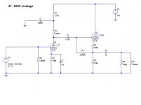
I am going to build a "simple" preamp 27 gain and some Octal follower.
What are peoples opinions on direct coupling vs. capacitor coupling?
I would like to use DC on the heaters and that pretty much means I need very low heater cathode differential on the follower.
I have heard many opinions that the 27 "likes" rather high plate voltage (180-250), this brings in the need for a cap coupling to lower the cathode voltage on 6SN7 follower.
Assuming I use high quality coupling cap is there really any distinct sound quality differences in Direct Coupling vs. Cap coupling?
One other advantage of the cap coupling will be lower B+ requirement, allowing me to use a Torroid transformer that I already own.
I will be using a similar tube based crossover (Pete Milett) for the mid/tweeter split. Thanks for the info. It will prove to be helpful on that project.
I have been "learning" LTspice and I thank Kevin and Jacques for the suggestion to "model" my designs. It has made designing infinately easier and "fun".
I have a question.
I am going to build a "simple" preamp 27 gain and some Octal follower.
What are peoples opinions on direct coupling vs. capacitor coupling?
I would like to use DC on the heaters and that pretty much means I need very low heater cathode differential on the follower.
I have heard many opinions that the 27 "likes" rather high plate voltage (180-250), this brings in the need for a cap coupling to lower the cathode voltage on 6SN7 follower.
Assuming I use high quality coupling cap is there really any distinct sound quality differences in Direct Coupling vs. Cap coupling?
One other advantage of the cap coupling will be lower B+ requirement, allowing me to use a Torroid transformer that I already own.
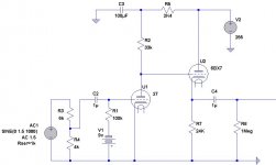
I think I have learned enough in LTspice to come up with this.
Sorry, all capacitors are too low!!!!
")
Francesco.
Sorry, all capacitors are too low!!!!
Francesco.
Francesco,
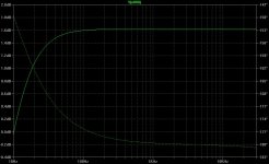
Perhaps the "format" of the Capacitor values was confusing. I reformatted them and attached the AC analysis.
It is down 1dB @ ~20hz by design.
Attachments
Francesco,
Perhaps the "format" of the Capacitor values was confusing. I reformatted them and attached the AC analysis.
It is down 1dB @ ~20hz by design.
Ok, now is better, but if you will obtain very good bass response on real load i suggest you must place C2X10 times and C4X5 times the actual values.
Sorry, all capacitors are too low!!!!
Francesco.
The values he cited in the schematic are pretty consistent with good practice in tube audio design. Unless he needs to drive loads appreciably below 50K the 1uF (C4) output coupling capacitor should be fine. The 0.1uF (C1) is an acceptable choice as well, if the LF pole needs to go lower the grid bias resistor can be increased - note also that because of the configuration there is some bootstrapping going on as well as long as the output is not excessively loaded. Note that C2 probably should be larger than 15uF (hard to find) because as the ac voltage across the capacitor increases some egregious internal distortion mechanisms come into play - note if you plan to use a film cap you can ignore the preceding as it applies only to electrolytics. (I'd use 100uF here if electrolytic) I would actually recommend trying fixed grid bias via battery. (Yes an input cap will be required)
Last edited:
Francesco,
I am hoping that the follower will help with overcoming my lack of funds for high quality interconnects. I also at this time have not determined the physical layout of where this equipment will reside, thus I might have a long interconnect run to the next stage.
It will primarily be used to amplify a PC sound cards output to a more useable level.
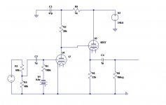
I prefer this type of layout as it is very "eligant" and "simple". I am modelling a similar cicuit with 6BX7 follower Direct Coupled to the the 27s plate output.
The less components in the signal path the better IMHO,
I am hoping that the follower will help with overcoming my lack of funds for high quality interconnects. I also at this time have not determined the physical layout of where this equipment will reside, thus I might have a long interconnect run to the next stage.
It will primarily be used to amplify a PC sound cards output to a more useable level.
I prefer this type of layout as it is very "eligant" and "simple". I am modelling a similar cicuit with 6BX7 follower Direct Coupled to the the 27s plate output.
The less components in the signal path the better IMHO,
Francesco,
The less components in the signal path the better IMHO,
That is because i suggest a single stage srpp preamp: this have also reasonable output impedance.
On the other hand, my friend tell me that the sound of 6BX7 is very very good.
Francesco.
That is because i suggest a single stage srpp preamp: this have also reasonable output impedance.
On the other hand, my friend tell me that the sound of 6BX7 is very very good.
Francesco.
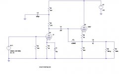
I have also heard that the 6BX7 is good. Attached is a schematic including the 6BX7 follower, direct coupling and Battery bias.
Attachments
UPDATE: Bought myself an Xmas Present!
Hello All,
I have been playing around with the idea to learn to play Bass Guitar, so i stopped into the local music shop to look at a "Beginner" bass.
Nothing caught my eye, BUT....In their used equipment section I found a Behringer FCA202 Firewire Audio "card".
Retail is $150USD I got it for $45!
The spec sheet is attached.
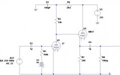
I wanted to "model" the pre-amp with this as the "source".
Since in Windows using ASIO drivers I have no volume control, I need a "master" volume control.
Could not find a "potentiometer" component in LTSpice so I modeled it as two resistors?
The data sheet indicates that the cards output is 2dBV (I assume 2V) since the driver control has the volume locked at about 75% I am safely assuming an output of 1.5V.
The sheet also indicated that the Output Z is about 1K so I specified the series resistance of the AC source to be 1K, is this a correct way to model it?
Any comments or suggestions are welcome as always!
Hello All,
I have been playing around with the idea to learn to play Bass Guitar, so i stopped into the local music shop to look at a "Beginner" bass.
Nothing caught my eye, BUT....In their used equipment section I found a Behringer FCA202 Firewire Audio "card".
Retail is $150USD I got it for $45!
The spec sheet is attached.
I wanted to "model" the pre-amp with this as the "source".
Since in Windows using ASIO drivers I have no volume control, I need a "master" volume control.
Could not find a "potentiometer" component in LTSpice so I modeled it as two resistors?
The data sheet indicates that the cards output is 2dBV (I assume 2V) since the driver control has the volume locked at about 75% I am safely assuming an output of 1.5V.
The sheet also indicated that the Output Z is about 1K so I specified the series resistance of the AC source to be 1K, is this a correct way to model it?
Any comments or suggestions are welcome as always!
Attachments
BTW - FYI,
The sound quality of the FCA202 with ASIO drivers compared to even a high quality PC sound card using WDM drivers is like NIGHT and DAY.
The firewire interface brings the Digital signal out of the PC case and to the FCA202's DA converter. The metal case and separate DC power supply cuts out ANY AND ALL Noise from the PC's Hard Drives, Power Supply, fans etc.
This is easily the BEST $50 I HAVE EVER SPENT!!
If you are looking for a quality "Sound Card" for your computer, (Kind of an Oxymoron) this is definately it!.
- Status
- This old topic is closed. If you want to reopen this topic, contact a moderator using the "Report Post" button.
- Home
- Amplifiers
- Tubes / Valves
- 27 & 6SN7 Preamp - Crossover