Kevin,
I have used similar couplings without the diode, I might just leave it out.
I know the phono stage itself is non inverting, but running it into the 27 inversion stage then inverts it the rest of the way to the amps. Since the amps I plan to use will be non-inverting and I would rather not have to invert the speaker leads I think I will increase the gain on the second stage of the phono section and bring the signal in to the grid of the follower. I can use a switch arrangement that "shorts" the input to the 27 and switches in the Phono lineout. I can then just add another 2 section pot to adjust the level of the Phono.
I do not have much experience with Phono Cartridges but my guess is that I can expect about 4-5mV? So overall gain of 500+ should be ok?
I'm a bit confused I guess - I had assumed that you had other sources which would also probably have non-inverting output phase in most cases. You can probably use the additional gain with the phono stage as opposed to the other line sources which are presumably a cd/dvd player with a nominal output of 2Vrms at FS.
Depending on cartridge 4 - 5mV @ 5cm/sec lateral recorded velocity is in the ball park (Grado certainly) but some high output MC and many MM are about 6dB lower than this. If you need 40dB of gain at 1kHz you will need ~60dB @ 20Hz to be close to RIAA equalization requirements at the low end. 40dB of gain incidentally will give you only about 400 - 500mVrms at the reference velocity (re 4 - 5mV) and 1kHz. It might be enough, but lower output cartridges could make the proposal marginal.
Then again depending on the speakers you use polarity may not be a big issue. I find only on a very small number of recordings I have that it matters - but it might be a function of the design of my speaker system which is multi-way (Onken 3 - way) with 2nd order butterworth x-o. (I think it is relatively linear phase, but not phase coherent - I didn't design it with that criteria in mind. I have measured FR which was reasonably flat, but I have no recollection of whether I measured the system phase response and if so what it was like.) So YMMV..
I trust your opinion and since my turntable is less than "ideal" I think I will just "live" with the inversion, which BTW as you point out will happen with the other sources anyway.
I have played around with this project in the planning stage so much that I lost track of where I was at. I had "tunnel" vision and only thought in terms of the "Phono" input.
I think it is now time to get out the soldering iron and get busy. I found an interesting source for chassis. Walmart has 9"x13" baking pans made of welded aluminized steel. They have a rolled lip on them and a quite sturdy and for $8 each sound good to me.
I figure I can make a nice hardwood base with a groove for the rolled lip. Considering a Hammond steel box is $26 they look like a bargain to me.
I plan to use a 6"x6" for the PS chassis and then the 9x13 for the preamp/crossover. I will start laying it out and see if I can comfortably fit the Phono section on the same chassis or maybe another 6x6?
I have just about used up my supply of NOS 6SN7's for this so maybe I go with 6J5 for the followers, or use 12SL7 & 12SN7 and use a 12VDC Regulated "wallwart" for the filaments on the phono preamp.
Clean DC to the filaments on the high gain phono section sounds like an idea to me?
")
Hi Coldcathode
Sorry not answering anymore, but I think you sorted things out for yourself! Good luck with the build!
to Albertli:
scroll down this page you find a link to a simple but effective X-over calculator (12 and 24dB LR). Just fill in two of the three values, and it will calculate the third for you!
Sorry not answering anymore, but I think you sorted things out for yourself! Good luck with the build!
to Albertli:
scroll down this page you find a link to a simple but effective X-over calculator (12 and 24dB LR). Just fill in two of the three values, and it will calculate the third for you!
scroll down this page you find a link to a simple but effective X-over calculator (12 and 24dB LR). Just fill in two of the three values, and it will calculate the third for you!
A Microsoft program, damn! Do you know of a Mac based calculator for a 24dB LR?
to Albertli:
scroll down this page you find a link to a simple but effective X-over calculator (12 and 24dB LR). Just fill in two of the three values, and it will calculate the third for you!
Eric,
As of site provided, I did the cal and found there might be some mistake on the R value on HP. If 22nf is used, the number of R I got was 72.34K, not 710K.
Please correct me.
Thanks
Albert
Eric,
As of site provided, I did the cal and found there might be some mistake on the R value on HP. If 22nf is used, the number of R I got was 72.34K, not 710K.
Please correct me.
Thanks
Albert
Albert,
Was is the desired crossover point you are looking for?
Albertli
use this link and download the capacitor program. It wil convert anything and everything as far as capacitor values.
cncfreak_capacitor_setup.zip
use this link and download the capacitor program. It wil convert anything and everything as far as capacitor values.
cncfreak_capacitor_setup.zip
Hello Albert,
This circuit is rather promising. You may tweak the circuit later with CCS and LED biasing later.
Johnny
Tang,
THANK YOU, I am glad that I am now actually designing circuits that are "promising"!
It has taken me a few years to get to this point. I have somewhat "Eclectic" tastes hence the mix of "odd tubes".
Due to the current economic times and my lack of employment, "designing" is what I can do for now. I am hoping to hear about a job soon and then get this thing built before Christmas.
I will be however preparing the chassis soon so I will post my efforts on that as I go.
Please ANYONE with any comments, suggestions, past experience etc. CHIME in!!
I think that I am not the only one who was looking for this as the START of a system. LED or Diode Biasing is an option along with a "Battery" I planned to explore those in the future also. CCS is a whole other arena I am staying out of for a while.
It is so sad that hearing people from losing their jobs. I just hope there will be a big turnabround coming soon. We do need a big change.
JOhnny
Johnny,
I have been out of work since October of 2008. I am waiting to hear about a job at a large Aviation manufacturer. What is so sad about the current economic times is that it did not have to happen.
Rather than get into a political discussion as to who is to blame I'll just point out a few facts. I see from your profile you are in Canada. So your wonderful neighbor to the south has screwed up your economy also.
The U.S. system is very successful and IMHO the best in the world. But, it has failings. These failings stem from diverging from the path originally set by the founders. Many people forget that it was not originally founded as a "two party" system. The current political landscape has placed an emphasis on "keeping" or "attaining" power and majority control.
This cannot be good for anyone. Even as a very "conservative" person I feel that complete control over all three branches of the US government by one party is DANGEROUS.
Examples of this are being seen today. The current Administration made POLITICAL decisions to campaign for office AGAINST the previous administration rather than against the opponent at the time. The BUSH administration was rather unpopular by that time (even amongst it's political bretheren). This resulted in the American people having to choose between the past policies and views (which were proven to be suspect) or a "HOPE" for a better tommorrow.
As a very OPTIMISTIC society America voted for Change and Hope without asking any questions about what that would cost both financially and in loss of freedoms. Politics in the US are very much like a "Pendulum". You cannot keep it to one side or the other for very long and when it swings back it swings farther to the opposite side.
The force of "gravity" had long been rooted in a sense of public service and decency in our officials of all political parties. Over time by pushing out any third or fourth parties to the system, the two major parties managed to make it just a "war" between "Good" and "Evil" or "black" and "white". Hence, we have gotten ourselves where we are today.
With no "middle ground" or "moderates" we have a "tug of war" for political control. Each side fighting to pull the pendulum in its direction rather than a force for the greater good trying to pull it towards the center and prosperity.
I truly believe we are headed towards a bit of a "revolution" in the US. The common man is sick and tired of BOTH parties.
Rather than get into a political discussion as to who is to blame...
This cannot be good for anyone. Even as a very "conservative" person I feel that complete control over all three branches of the US government by one party is DANGEROUS.
Examples of this are being seen today. The current Administration made POLITICAL decisions to campaign for office AGAINST the previous administration rather than against the opponent at the time. The BUSH administration was rather unpopular by that time (even amongst it's political bretheren). This resulted in the American people having to choose between the past policies and views (which were proven to be suspect) or a "HOPE" for a better tommorrow.
A thread discussing a tube crossover is no place for a political diatribe such as this.
Please take it elsewhere.
Update: A secondary project Schematic.
Hello All,
Updates:
1: I have gotten a new job! Will be working for Sikorsky Aircraft (makers of the Black Hawk and Super Stallion)
2: I put the 27 Xover pre project "on hold" while awaiting the PC boards for the subwoofer Tube/Chipamp Hybrid that goes with it.
I recently "inherited" a pair of old "high end" Ratshack (Radio Shack) speakers that were my Father In-Laws. These were very rarely played, they are very nice little book shelf type speaker with a high sensitivity. I am putting together a PP amp with 1625's (807's) "Triode Strapped". The "war dept." (WIFE) has approved them to go in the living room to amplify the Plasma TV and play CD's.
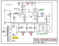
I was looking to build a simple linestage with nice aesthetics to give a little "push" of the CD/DVD player outputs.
I went thru my "tube collection" and happened across a few 56 and 76 tubes. Attached is the schematic for one channel.
Comments, suggestions, did I miss anything?
Hello All,
Updates:
1: I have gotten a new job! Will be working for Sikorsky Aircraft (makers of the Black Hawk and Super Stallion)
2: I put the 27 Xover pre project "on hold" while awaiting the PC boards for the subwoofer Tube/Chipamp Hybrid that goes with it.
I recently "inherited" a pair of old "high end" Ratshack (Radio Shack) speakers that were my Father In-Laws. These were very rarely played, they are very nice little book shelf type speaker with a high sensitivity. I am putting together a PP amp with 1625's (807's) "Triode Strapped". The "war dept." (WIFE) has approved them to go in the living room to amplify the Plasma TV and play CD's.
I was looking to build a simple linestage with nice aesthetics to give a little "push" of the CD/DVD player outputs.
I went thru my "tube collection" and happened across a few 56 and 76 tubes. Attached is the schematic for one channel.
Comments, suggestions, did I miss anything?
Attachments
Revised the two schematics, including a diode to protect the first 6SN7 from cathode stripping at turn on, but I can't come up with a way to protect the HP follower?
Also, made major changes to design of the Phono section but just now noticed that when in Phono mode the signal will be inverted relative to "normal" because of the odd number of gain stages. Any suggestions?
The only other idea I had was to bypass the Rk on the 2md phono gain stage (thus doubling gain) and recalc the RC values for that pole, then I could bring it's signal in at the junction of the 27 with the SN7 follower?
Hello,
Congratulations on the new job. What a great Christmas present!
This is a comment about your 27 crossover. Have you modeled this circuit? If you do I think you will find that the stopband attenuation of the low pass section is only about -40dB. This occurs because the output buffer has a highish output impedance (400 ohms or so) and at high frequencies the feedback capacitor will shunt across the output buffer causing the input to appear (attenuated) across the output impedance. That can be addressed by providing a separate buffer for the feedback capacitor in the LP section.
This particular defect is present to some extent in all Sallen-Key implementations, but is reduced as the output impedance of the buffer gets closer to zero.
Here is a link to a post in a thread for a solid-state project with similar topology showing a solution.
For a more general discussion of the topic, refer to this article in EDN.
Nice project.
Cheers,
Jacque has a rather strong point about the importance of low output Z with VCVS (Sallen-Key) filter implementations.
Higher transconductance types than the 6SN7 will also help here, think 5842 for example. I would also check out the 5687 dual triode, it might also work well. (IIRC in spice models for an active x-o project I subsequently abandoned it seemed to be a significant improvement)
Other types worth further investigation include the following high transconductance pentodes: D3A, 6688, 7788 whether triode connected or operated as pentode connected cathode followers. IMO pentode followers could prove to be very interesting.. (Theoretically output Z should be much lower than achieved in triode connection.)
Kevin - Jacques,
I have NO experience with Spice modeling at all. I can work with Ohm's law (backwards and forwards), use plate curves, calc gain, miller, etc...all the usual calculator and paper type math.
I "think" I have my hands around the issue. The 33nF cap and the Output Z of the follower form a Pole with F3 of about 12Khz. You are saying somehow this affects the crossover total "blocking"? So at say 93hz we are down 7 octaves so 42dB?
Am I understanding this correctly or am I off base? Theoretically getting the output Z down to 10R would put the F3 at 480Khz so at 93 we are down about 12 octaves so 72dB?
I read the attached info, could I use a SS Op-amp somehow?
Or an additional tube?
How would I do this?
- Status
- This old topic is closed. If you want to reopen this topic, contact a moderator using the "Report Post" button.
- Home
- Amplifiers
- Tubes / Valves
- 27 & 6SN7 Preamp - Crossover