Kevin - Jacques,
I have NO experience with Spice modeling at all. I can work with Ohm's law (backwards and forwards), use plate curves, calc gain, miller, etc...all the usual calculator and paper type math.
I "think" I have my hands around the issue. The 33nF cap and the Output Z of the follower form a Pole with F3 of about 12Khz. You are saying somehow this affects the crossover total "blocking"? So at say 93hz we are down 7 octaves so 42dB?
Am I understanding this correctly or am I off base? Theoretically getting the output Z down to 10R would put the F3 at 480Khz so at 93 we are down about 12 octaves so 72dB?
I read the attached info, could I use a SS Op-amp somehow?
Or an additional tube?
How would I do this?
I don't think that's quite it. Take look at the EDN article, esp Figure 3 which shows the shunt path.
Anyway, there are primarily two ways to address this. One is to decrease the cathode follower Zout and/or increase Rfb. It is primarily the ratio of Zout to Rfb that determines the stopband attenuation. The other way is to provide an additional buffer for the feedback cap. This could be solid state, which I am assuming you would like to avoid
") Or it could be another cathode follower. If you add another buffer then the output impedance of the buffer becomes less important.
Or it could be another cathode follower. If you add another buffer then the output impedance of the buffer becomes less important.Let me model this and get back to you. Unless Kevin beats me to it
.Cheers,
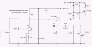
hi Coldcathode, many years ago i have realized a preamp tube much similar to your last attachment.
The second stage employes a 7044, that is equivalent of the 5687, but it's specifically suitable as follower, because it can support double cathode-filament voltage (200 V) against 100 V of 5687.
Regards, Francesco.
The second stage employes a 7044, that is equivalent of the 5687, but it's specifically suitable as follower, because it can support double cathode-filament voltage (200 V) against 100 V of 5687.
Regards, Francesco.
Attachments
hi Coldcathode, many years ago i have realized a preamp tube much similar to your last attachment.
The second stage employes a 7044, that is equivalent of the 5687, but it's specifically suitable as follower, because it can support double cathode-filament voltage (200 V) against 100 V of 5687.
Regards, Francesco.
Francesco,
I see why you would want that high spec on the heater-cathode voltage. I am now "PUSHING the ENVELOPE" with the cathode at 111V.
What Plate voltage and current is the 76 running at?
How was the sound.
Did you try it with unbypassed Rk? or did you need the greater gain?
I think I have some 7044's (IBM maybe?)
I prefer the Octals but since the 76/56 are St shape I guess the followers do not really matter anyway. LOL
Hi, for maximize the linearity of the 76 tube, the supply voltage is better higher in value: in this case is 365V. So the cathode voltage of 7044 is near 180 V.
76 tube is a very low mu triode, but if you not need much gain, you can omit the 470mF bypass cap
Francesco.
Last edited:
Let me model this and get back to you.
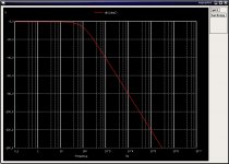
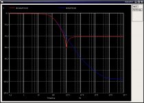
Here are the results of the simulation. The first plot (ideal.jpg) shows the ideal response of the low pass section (i.e. zero output impedeance of the output buffer). The second plot (actual.jpg) shows the response of the low pass section as you have drawn it (about 41 dB stopband attenuation), and with an additional buffer isolating the feedback capacitor from the filter output. The version with the additional buffer follows the ideal response pretty closely down to about -80 dB or so, after which point it deviates more significantly.
Reducing the output impedance of the buffer is another approach. In that case it would take about a 10 fold increase in transconductance of your output tube to effect a 20 dB improvement in stopband attenuation.
Hope this helps.
Attachments
Jacque,
Suppose I would "accept" using an Opamp? What would the circuit look like and which Opamp do you reccomend?
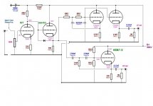
I would recommend that you consider something like this with an additional cathode follower rather than use an op-amp. This is the configuration of the "buffered" circuit I ran the simulation on.
Attachments
I would recommend that you consider something like this with an additional cathode follower rather than use an op-amp. This is the configuration of the "buffered" circuit I ran the simulation on.
Jacques,
Something like this?
I might change the tubes a bit, 6BX7 have a higher Heater-cathode voltage tolerance lower Rp and higher Gm. If I have enough of them in my drawers I might go that way.
More concerned with the topology right now the specifics can wait.
I thank you very much for your assistance.
Attachments
All,
Attached is a quick schematic of a PS for the Xover project. I would like to "lift" the 6SN7 follower's Heaters since the cathodes are at 155+V. (Vintage NOS Tung-Sol 6SN7WGTA's).
The heater winding on the Power Xformer does not have a CT.
In pink on the schematic I show a "tap off" of +150V from between the (2) VR tubes. Is this "OK", do I need a current limiting resistor? a small cap?
Should I just use a Voltage Divider from B+?
Lifting heaters is new to me.
Can't upload picture???
Thanks,
Last edited:
Jacques,
Something like this?
I might change the tubes a bit, 6BX7 have a higher Heater-cathode voltage tolerance lower Rp and higher Gm. If I have enough of them in my drawers I might go that way.
More concerned with the topology right now the specifics can wait.
I thank you very much for your assistance.
Yes, that's what I meant. Bear in mind that this does not address the issue raised by SY, which should be taken seriously. That particular issue is new to me and I will be spending some time to get my head around it.
Good luck,
Yes, that's what I meant. Bear in mind that this does not address the issue raised by SY, which should be taken seriously. That particular issue is new to me and I will be spending some time to get my head around it.
Good luck,
Jacque,
My system is hardly a "low distortion" high end audiophile system. I will look into SY's suggested reading and look at the distortion issue. I assume he is stating that distortion @ and about the Xover point is increased by a factor of 10x?
So 0.2% = 2% THD?
Please comment also on the Heater Lifting.
Attachments
Before embarking on a Sallen-Key crossover, I would carefully read the Billam paper (JAES v26 n6, p426, 1978), noting the two order of magnitude distortion increase in the crossover region.
SY...Anyone
I am not a member of AES and cannot afford to join and subscribe.
Does anyone have the text of this article to share with me?
There is also a similar article written by Billam in IEEE Journal of SS Circuits
August 1979, Volume 14 p768 titled "Practical optimization of noise and distortion in Sallen and Key filter sections"
This article might be of even more use in this project.
Jacque,
My system is hardly a "low distortion" high end audiophile system. I will look into SY's suggested reading and look at the distortion issue. I assume he is stating that distortion @ and about the Xover point is increased by a factor of 10x?
So 0.2% = 2% THD?
Please comment also on the Heater Lifting.
Two orders of magnitude is actually 100X - the op-amps normally used in VCVS filters have distortion levels several orders of magnitude lower than your tube based buffers.
Spice does predict an increase in thd in the x-o region, but I do not recall it being this severe (although it wasn't too great either) - I had other problems that prompted me to eventually abandon the effort.. IIRC Higher Q implementations make the problem much worse - Q was about 0.707 (Butterworth) and my recollection is I thought at the time that it was an acceptable compromise.
FWIW I also found that using passive LCR based networks as less practical than I hoped because of the impedances involved.
Somewhat related but oriented to passive loudspeaker X-O design: http://www.audioholics.com/education/loudspeaker-basics/filter-crossover-types-for-loudspeakers
Last edited:
Two orders of magnitude is actually 100X - the op-amps normally used in VCVS filters have distortion levels several orders of magnitude lower than your tube based buffers.
kevin,
Thanx, my math skills sometimes fail me. I was thinking in terms of 2x10...DUH!! rather than 10x10 LOL
I am wondering why I have seen many designs similar to this but have not heard of any distortion or stop band issues?
I am in no way "doubting" Jacques or SY's implications I am just confused as to the severity of the issues or the "less discerning" ears of the other designers.
If I am going to go through all the trouble and expense of this project then I might as well "lean on" the support from much more experienced people such as yourself.
Having "employment" in the near future has definitely changed my outlook on how to approach this. I think I will "jump in feet first" and do this as close to "ideal" as possible.
MAYBE I need to "approach" these issues in a different way.
Can anyone suggest a "Free" or "Low Cost" version of SPICE that is rather "intuitive" for a spice beginner?, and tube circuit analysis?
I have recently started using a program called "Curve Captor" mostly for the "modeling" of power stages. It does have a "nice" feature to create spice models by "tracing" curves from data sheets.
It sure beats "paper and pencil" methods for plotting load lines!!!
Congrats on the job, while it is not intuitive it is free and excellent, I am of course talking about LTSpiceIV available here: http://www.linear.com/designtools/software/ltspice.jsp
There are a lot of people using it here, the tube libraries are readily available - look for my old posts on LTSpice, you should find my libraries as well as instructions on how to install them.
I was going to recommend Spectrumsoft's Micro-Cap, but you can no longer download the student version anonymously, link here: Micro-Cap Evaluation Program From Request Note that this evaluation/student version is extremely crippled so I don't really recommend it as being worth the effort. (I used this before LTSpice became available which was quite a long time ago.)
WRT to the issues Jacque and SY have raised, some of them are why I abandoned my effort along with a concern that the additional signal path complexity might prove less kind to the music than my rather decent butterworth homebrew passive speaker level x-os..
For sub-woofing of course even an op-amp implementation is fine, above that I think I prefer simple 1st order passive x-o ahead of the power amplifier (capacitors)
Passive electronic X-O are somewhat practical if you can wind your own inductors for use at around 600 ohms or less. Transformer coupled electronics become necessary if you take this approach.. (Which pretty much describes my system these days.) Input transformers are not required but the amplifier inputs must provide 600 ohm terminations.
Mind you, I'm not certain that lower order vcvs (sallen-key) tube based x-o can't be made to work well, but the issues are none trivial to solve and fly in the face of my desire for simplicity where possible. Spice analysis (assuming good tube models) will allow you to intelligently choose your trade-offs..
Note that you might want to look at multiple feedback filters as well, I will warn you however that they are not very analysis friendly, but do not suffer from the same limitations as the VCVS. (They're just really unfriendly to understand OUCH!) Spice analysis tools are mandatory as is some understanding of the mathematical relationships between the various poles and zeros in the filter implementation. I've used them, never really understood them well, and probably will avoid them for the balance of my existence..
Last edited:
Kevin,
Thanks alot, I will try out LTSpice.
I am not totally against using solid state components BUT I prefer tubes because of the "challenge".
If the analysis of this model shows too much distortion I have always considered just using a 1st order RC passive between two followers and then again at the input to the amplifiers.
I resisted going in that direction straight out of the blocks because I would rather avoid having any of the Xover circuitry in the amplifier itself. I even thought about trying to bring the Miller Cap into the equation on the Low Pass channel, but I would need a tube with high miller and high stage gain to even get to a "tweeter" amp point.
Billam's paper showed a distortion increase of about 80x. I was never happy with the sound of most tube Sallen-Key crossovers I had built, and I've heard similar comments from others- EC8010 put me on to Billam's paper and the light went on for me.
Whether you use an S-K or not, the cathode followers should use a high transconductance triode, preferably one with a reasonably high mu. 7788, D3a, or the like would be ideal, Ecc88 or similar will be nearly as good. 6SN7 has mediocre transconductance, 6080 has very low gain. Neither are a good choice for a crossover, though the 6SN7 makes an excellent voltage amp.
Whether you use an S-K or not, the cathode followers should use a high transconductance triode, preferably one with a reasonably high mu. 7788, D3a, or the like would be ideal, Ecc88 or similar will be nearly as good. 6SN7 has mediocre transconductance, 6080 has very low gain. Neither are a good choice for a crossover, though the 6SN7 makes an excellent voltage amp.
I downloaded LT spice.
How do I define a triode? I have already fumbled my way thru an AC simulation of a basic RC filter. I have a "model"
.subckt 6sn7 P G K
Bp P K I=(0.02003791851m)*uramp(V(P,K)*ln(1.0+(-0.07740549711)+exp((4.618036737)+(4.618036737)*((20.85288965)+(-110.4389272m)*V(G,K))*V(G,K)/sqrt((28.13407639)^2+(V(P,K)-(7.118597372))^2)))/(4.618036737))^(1.380047579)
Cgp G P 4.0pF
Cgk G K 2.6pF
Cpk P K 0.7pF
.ends 6sn7
How do I attach the above info to the triode component?
Please comment also on the Heater Lifting.
I do think that lifting the 6SN7 cathode follower heater supply to +100V is a good idea. In your sketch it appears that the 6SN7 heater supply is still connected to ground. I would probably use a separate 6.3 volt CT transformer for the 6SN7s. I would connect the heater CT to a resistive divider between B+ output and ground. Two equal value resistors of 1 Megohm should be fine.
It is usually not a good idea to operate separate tube heaters in series other than for tubes which are specifically designed to be operated that way. IIRC, those were usually TV tubes spec'd as "designed for series-string operation". I would probably use a separate 2.5 Volt CT filament transformer for each 27, with the CT connected to the cathode, as described in the RCA datasheet.
The Sallen-Key distortion issue is new territory for me. One one hand, I have the impression that quite a number of well received products utilize the Sallen-Key configuration. Linkwitz, for one, seems to think it's fine. On the other hand, it would be imprudent to ignore SY's and other negative comments about it.
I don't have a copy of Billam's paper either. Does anyone (SY ?) have a copy they would be willing to forward to me?
In any event, I probably won't get to spend much time thinking about this until after Christmas. Family obligations, you know
.Thanks,
- Status
- This old topic is closed. If you want to reopen this topic, contact a moderator using the "Report Post" button.
- Home
- Amplifiers
- Tubes / Valves
- 27 & 6SN7 Preamp - Crossover