Never actually done this, only read Dr Hurst's publications.
If Damir will post the ASC then I will post how it works out.
Best wishes
David
Hi David,
Have you tried it?
Best regards
Damir
Hi David,
Have you tried it?
Not yet, sorry.
Have spent the day on a Harman Kardon AVR230 that refuses to work.
If the digital controller has problems then the entire amp is useless.
The back-up battery for the digital board is soldered in and can't be replaced without major disassembly.
And the electrolyte has leaked over the PCB.
So a simple battery failure ruins the entire amp.
No way just to input a simple analog signal to the power amp section.
Really bad product, has killed my enthusiasm for amplifiers for a few days.
Best wishes
David
No hurry here, I am sorry that a bad product ruined your day.
Yesterday I had a problem with my Mordount-short subwoofer. They use 0.1u ceramic caps parallel to the diodes in the power rectifier and two shortened and the fuses blown.
I don't know why they put it there in first place and then os such bad quality.
Happy New Year to you David
Damir
This similar CFA amp with simplified compensation, but now with vertical MOSFET OPS. It simulates a bit lower distortion and less sensitive on capacitive load.
Damir
Damir
Attachments
Nice CFA design !
Happy New Year !!!
-Richard Marsh
Thank you Richard,
and Happy New Year!
Damir Verson
Today I have been reading through this thread, very impressive work! I've been seeking a high performance amplifier design of around 100W into 8R to build a 6 channel poweramp for tri-amplified system. This appears to fit the bill!
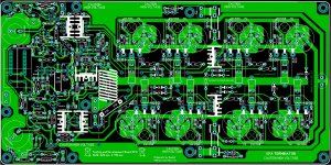
I am glad the 100W version wasn't overlooked, congratulations on your layout Krisfr, it looks good on brief inspection! Appears to be several duplicate component designators on the silkscreen though, all of the capacitance multiplier parts and R10. I would go in for a group buy on this design and I expect there are others who would do too. Is the design that of post 136 ?
I like the relay drive output that nattawa used in his SMT design, it is a worthwhile addition IMO and a much better approach than to put a relay on the PCB. I would have the option to use this output to drive a solid state relay, probably via a microcontroller monitoring loss of AC and other parameters")
Keep up the good work, if you don't want to re-visit the 100W version then maybe I will consider building a 6 x 200W beast
EDIT: I am also interested in the noise performance of the amplifier, residual output noise and SNR. There was some brief discussion earlier and it led to me believe it may be superior in this CFA design than many VFA designs?
Is this okay?
I want to complete this POC so the 200 Watter can make my speakers SING
I am glad the 100W version wasn't overlooked, congratulations on your layout Krisfr, it looks good on brief inspection! Appears to be several duplicate component designators on the silkscreen though, all of the capacitance multiplier parts and R10. I would go in for a group buy on this design and I expect there are others who would do too. Is the design that of post 136 ?
I like the relay drive output that nattawa used in his SMT design, it is a worthwhile addition IMO and a much better approach than to put a relay on the PCB. I would have the option to use this output to drive a solid state relay, probably via a microcontroller monitoring loss of AC and other parameters
Keep up the good work, if you don't want to re-visit the 100W version then maybe I will consider building a 6 x 200W beast
EDIT: I am also interested in the noise performance of the amplifier, residual output noise and SNR. There was some brief discussion earlier and it led to me believe it may be superior in this CFA design than many VFA designs?
Last edited:
Today I have been reading through this thread, very impressive work! I've been seeking a high performance amplifier design of around 100W into 8R to build a 6 channel poweramp for tri-amplified system. This appears to fit the bill!
I am glad the 100W version wasn't overlooked, congratulations on your layout Krisfr, it looks good on brief inspection! Appears to be several duplicate component designators on the silkscreen though, all of the capacitance multiplier parts and R10. I would go in for a group buy on this design and I expect there are others who would do too. Is the design that of post 136 ?
I like the relay drive output that nattawa used in his SMT design, it is a worthwhile addition IMO and a much better approach than to put a relay on the PCB. I would have the option to use this output to drive a solid state relay, probably via a microcontroller monitoring loss of AC and other parameters
Keep up the good work, if you don't want to re-visit the 100W version then maybe I will consider building a 6 x 200W beast
EDIT: I am also interested in the noise performance of the amplifier, residual output noise and SNR. There was some brief discussion earlier and it led to me believe it may be superior in this CFA design than many VFA designs?
Thank you for your opinion. This amp is easy to scale down to the 100 W, just use half of the OPS, and lower power supply voltage to +-50 V.
Regarding protection, I designed a power supply regulator with all protection you need, look here http://www.diyaudio.com/forums/solid-state/182554-thermaltrak-tmc-amp-17.html#post3167481.
I use it every day in my TT amp(the same thread as the regulator) with no problem at all, ones it saved my loudspeaker becouse of bad solder in the amp.
Damir
Dadod will your regulator work okay at higher voltage. Such as +- 60 or 70 or even 80?
Yes it will, it's quite independent of the input voltage, just it needs to be scaled for output current. For higher voltage it could need to change some transistors for higher voltage type.
dadod, you`re a clever guy, but beware, simulating and chasing numbers it`s like coke
Cheers!
Thank you Bogdan. If you meant this particular amp, you are correct, I did not build it yet, but I have built many others after I simulated them and they worked with no problem.
Speaking of building, I am going to etch this puppy sometime soon and fire up the old lead tin melter. Please advise of any mistakes... the silk screen is not good for the OPS, I wish I could print it on this Single Sided Board. Anyone know of some trick to print in any light color ? Maybe I could get Staples to print a reverse in White on a laser printer...Ummmm
Attachments
Hi David,
Here it is, and the best wishes and happy New Year to all!
Thanks for help
Damir
By mistake .asc file was wrong, instead OIC it was MIC, here is correct one.
David sorry if you started to analyze wrong one.
BR Damir
Attachments
...David sorry if you started to analyze...
No problem. Have not started analysis.
Have the theory but need to work out the test circuit implementation, have a post about that.
Best wishes
David
This amp use OIC(output inclusive compensation) and in smaller part Miller compensation(15p//150ohm x 2). As in other thread ongoing discussion about ULGF points that Unity Loop Gain Frequency(ULGF) should not be above OPS pole, I simulated the Loop Gain(LG) with different value for the OIC capacitor and have found something what looks contra intuitive. When I started with this amp my goal was to have good THD figures, and excellent Phase Margin(PM) and Gain Margin(GM), and from simulation it came the best value for OIC capacitor, C8 in the schematic, of 100 pF. Because of quite high ULGF (6.4 MHz) I tried to lower it. What surprised me that lower C8 value lowers the ULGF, I expected just opposite. Here LG were simulated with three C8 values. Distortion stays almost the same, ULGF was almas halved, PH a bit lower and GM improved.
I am quite confident that this amp even with C8 of 100 pF is stable, I simulated it at full power, end clipping, with different capacitive load and it shows no hint instability( with no output inductor it is stable up to 270 nF), and C8 of 47 pF is the best choice.
BR Damir
I am quite confident that this amp even with C8 of 100 pF is stable, I simulated it at full power, end clipping, with different capacitive load and it shows no hint instability( with no output inductor it is stable up to 270 nF), and C8 of 47 pF is the best choice.
BR Damir
Attachments
Hi Dadod,
I could be wrong, but are we looking at the global loop response by putting the Tian Probe there? Perhaps we are in fact looking at one of the "inner loops"?
I found in my simulation (of a slightly different version schematic) that by having the Cherry cap take up feed back straight from the output node instead of the left side of the Tian Probe, which I thought to be the way to examine an "outer loop" response, it makes a huge difference to the loop response result. The loop would then close at about ULGF = 1.73MHz and GM sit at about 16dB. And by increasing the value of the Cherry cap the ULGF would go lower.
Perhaps simulation gurus could chime in and offer some hint?
Hi Dadod,
I could be wrong, but are we looking at the global loop response by putting the Tian Probe there? Perhaps we are in fact looking at one of the "inner loops"?
I found in my simulation (of a slightly different version schematic) that by having the Cherry cap take up feed back straight from the output node instead of the left side of the Tian Probe, which I thought to be the way to examine an "outer loop" response, it makes a huge difference to the loop response result. The loop would then close at about ULGF = 1.73MHz and GM sit at about 16dB. And by increasing the value of the Cherry cap the ULGF would go lower.
Perhaps simulation gurus could chime in and offer some hint?
Hi Nattawa,
I did the simulation both way, and I think that "outer loop" response does not say enough about stability. I used similar approuch to simulate VFA amps with TMC and never had any problem when I built that amp.
I you are correct, even better, then ULGF is not above OPS pole.
David promised to do some more dip simulation(I am not that good in spice) and we will see more clearly what is going on.
Hi Nattawa,
I did the simulation both way, and I think that "outer loop" response does not say enough about stability. ........
You're right about that, Dadod. I too found it necessary to check all loops for instability, just like all the gurus have pointed out. In a VFA amp with TMC I'm currently putting together I found a phase dip dangerously approching -170 degrees while loop gain is high up at 50+ dB in an inner loop, yet the outer loop plot shows no signs of such danger at all.
You're right about that, Dadod. I too found it necessary to check all loops for instability, just like all the gurus have pointed out. In a VFA amp with TMC I'm currently putting together I found a phase dip dangerously approching -170 degrees while loop gain is high up at 50+ dB in an inner loop, yet the outer loop plot shows no signs of such danger at all.
You don't need to wary about that phase dip with TMC, it could come close to -180 degree without stability problem. To meliorate that dip add capacitor in serie with TMC resistor, or bridge the TMC caps with small one, but in this case you are losing some gain at 20 kHZ.
BR Damir
- Home
- Amplifiers
- Solid State
- 200W MOSFET CFA amp