Yes, it can be used, anything with smaller diameter of 0.22mm will do the job for this converter.
Check this link:
American Wire Gauge table and AWG Electrical Current Load Limits with skin depth frequencies and wire breaking strength
Check this link:
American Wire Gauge table and AWG Electrical Current Load Limits with skin depth frequencies and wire breaking strength
Some misbeliefs live forever.
On what exactly did you mean?
It is the same as tubing, with some isolating hose/tube.Sorry, I don't know what hosing mean. Especially in connection with litz wire. Could you explain it?
The belief that skin effect is the major problem. Indeed it is here of minor importance, proximity effect is the one that makes your windings melt.On what exactly did you mean?
You will even notice differences when changing litz wires from 0.1mm strands to 0.05mm strands
It is the same as tubing, with some isolating hose/tube.
Yes, it reduces proximity effect, but needs more space, so bigger core. (Or smaller copper cross-section, but it would increase simple resistive loss.)
And if you have a bigger core, then the optimal placement of the wire is that you avoid the area where the stronger (leakage and fringing) flux arises: above gap, and between primary and secondary. In these "empty" spaces the magnetic energy can be stored without loss.
Last edited:
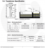
For this 200W converter I chose slightly bigger ferrite core ETD39 than required for that power and there is additional unused space on bobbin which can be used in a case of some additional windings isolation or larger diameter of wires.
In most application notes for this range of power and working frequencies for LLC, manufactures advice to use standards Litz wires without additional insulation (hose/tube).
For higher power and frequencies, manufactures advice to use planar transformers with PCB windings.
In most application notes for this range of power and working frequencies for LLC, manufactures advice to use standards Litz wires without additional insulation (hose/tube).
For higher power and frequencies, manufactures advice to use planar transformers with PCB windings.
Thats OK. 0.12 mm diameter is usable. But is eddy current negligible here? Not.
And in the datasheet of the same part they recommend 0.08 mm x 88 for primary:
http://www.mouser.com/ds/2/149/FSFR2100-1010133.pdf
And in the datasheet of the same part they recommend 0.08 mm x 88 for primary:
http://www.mouser.com/ds/2/149/FSFR2100-1010133.pdf
Because the maximum frequency is quoted as 300kHz.they recommend 0.08 mm x 88 for primary:
What does "Not." mean?But is eddy current negligible here? Not.
Thanks Pafi - this is what I learned meanwhile by reading some stuff about proximity effect.Yes, it reduces proximity effect, but needs more space, so bigger core. (Or smaller copper cross-section, but it would increase simple resistive loss.)
And if you have a bigger core, then the optimal placement of the wire is that you avoid the area where the stronger (leakage and fringing) flux arises: above gap, and between primary and secondary. In these "empty" spaces the magnetic energy can be stored without loss.
I am aware that tubing reduces effective copper area. But under certain conditions this can be advantageous. With heat shrinked tubed litz wire I got the lowest temperature rise at 130kHz working frequency and wondered how this could be.
Voltwide,
I agree, it can help reducing temperature, just I think it could be even better if the isolated spaces were placed where the strongest flux is. By placing primary and secondary wires to opposite ends of the coil former the leakage flux can be increased without generating heat. Thanks to this number of turns can be decreased, therefore generating less heat. Not a strong effect, but it is for free.
I agree, it can help reducing temperature, just I think it could be even better if the isolated spaces were placed where the strongest flux is. By placing primary and secondary wires to opposite ends of the coil former the leakage flux can be increased without generating heat. Thanks to this number of turns can be decreased, therefore generating less heat. Not a strong effect, but it is for free.
Because the maximum frequency is quoted as 300kHz.What does "Not." mean?
300 kHz is the maximum freq of the IC, not the actually designed circuit. Max operating freq of the template design is about 180 kHz. And minimum freq, what corresponds to maximum power is about 80 kHz. This is the freq the transformer is designed for.
Not means denial answer for the preceeding question.
How are things going?
Now, this: http://www.audiophonics.fr/images2/6189/SMPS300R.pdf
I'd like to know what you think of this schematic... same manufacturer as the PSU I tested and which utterly failed at being "low noise". I'm not going to get suckered again and buy this one though...
Now, this: http://www.audiophonics.fr/images2/6189/SMPS300R.pdf
I'd like to know what you think of this schematic... same manufacturer as the PSU I tested and which utterly failed at being "low noise". I'm not going to get suckered again and buy this one though...
@savu
I didn't test this converter with such extremes, only up to around 200W without heatsink on FSFR.
I didn't find solution to make single layer PCB and to make space for heatsink because that will drastically change components placement, will have larger power loop and that will cause larger EMI emission, I tried to keep it as small as possible.
Yu3ma, try this supplier for 2 sided PCB. A friend works with them and he seems very satisfied by the price and quality of the pcbs
PCB Prototyping
PCB Prototyping
- Status
- This old topic is closed. If you want to reopen this topic, contact a moderator using the "Report Post" button.
- Home
- Amplifiers
- Power Supplies
- 200W LLC ZVS Power Supply with FSFR2100XS