Hello everyone,
I presenting here OSHW DIY project for 200W LLC PSU based on FSFR2100XS power controller.
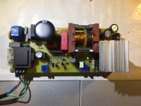
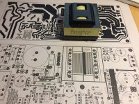
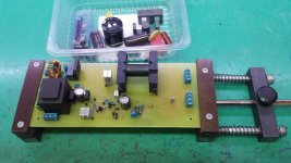
Construction utilize single layer PCB for easy build and combine SMD and TH components.
On GitHub page you can find all relevant documentation including source files for PCB and SCH:
https://github.com/yu3ma/FSFR2100_LLC_SMPS
This converter do not utilize PFC, it is optimized only for 230VAC mains input.
The converter specification data are the following:
Nominal input voltage: 325VDC (230VAC)
Maximal input voltage: 355VDC (250VAC)
Minimal input voltage: 295VDC (210VAC)
Brwown-out: 260VDC (184VAC)
Output voltage 1: +/-28V 3A
Output voltage 2: +/-14V 1A
Resonance frequency: 85 kHz
Max operating frequency: 250 kHz
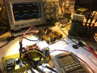
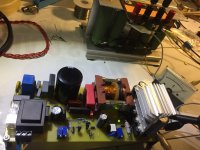
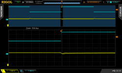
PS: This converter is build with educational purpose in mind, it have various test points and auxiliary PS for testing under controlled environment in various regimes under open or closed loop feedback. The goal is to learn and test basic operational principles of LLC resonant converters so you will probably need oscilloscope and/or LRC meter for setting correct working parameters of converter. Construction can be used for any other voltage combination but you need to recalculate new integrated transformer by yourself. LLC converters can look bit complex but in core they are quite simple and once you learn how they work you will be surprised by results, how efficient and quite it can be!
Some photos in attachment.
I presenting here OSHW DIY project for 200W LLC PSU based on FSFR2100XS power controller.
Construction utilize single layer PCB for easy build and combine SMD and TH components.
On GitHub page you can find all relevant documentation including source files for PCB and SCH:
https://github.com/yu3ma/FSFR2100_LLC_SMPS
This converter do not utilize PFC, it is optimized only for 230VAC mains input.
The converter specification data are the following:
Nominal input voltage: 325VDC (230VAC)
Maximal input voltage: 355VDC (250VAC)
Minimal input voltage: 295VDC (210VAC)
Brwown-out: 260VDC (184VAC)
Output voltage 1: +/-28V 3A
Output voltage 2: +/-14V 1A
Resonance frequency: 85 kHz
Max operating frequency: 250 kHz
PS: This converter is build with educational purpose in mind, it have various test points and auxiliary PS for testing under controlled environment in various regimes under open or closed loop feedback. The goal is to learn and test basic operational principles of LLC resonant converters so you will probably need oscilloscope and/or LRC meter for setting correct working parameters of converter. Construction can be used for any other voltage combination but you need to recalculate new integrated transformer by yourself. LLC converters can look bit complex but in core they are quite simple and once you learn how they work you will be surprised by results, how efficient and quite it can be!
Some photos in attachment.
Attachments
Last edited:
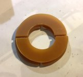
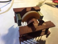
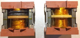
Some details on integrated transformer, DIY split bobbin on standard ETD39 with gapped 3F3 core.
Parasitic capacitance from primary to secondary windings is very very low, around 5pF!
Parasitic capacitance from primary to secondary windings is very very low, around 5pF!
Attachments
Last edited:
@nigelwright7557
Yes, LLC is very nice working topology.
Can You please share some details about your construction, schematic for example?
And can you explain this "I used a PIC micro to generate the two LLC frequencies", which two frequencies, what about frequencies in between?
Yes, LLC is very nice working topology.
Can You please share some details about your construction, schematic for example?
And can you explain this "I used a PIC micro to generate the two LLC frequencies", which two frequencies, what about frequencies in between?
I agree that LLC looks like a very promising topology specially as a supply for audio amplification. Low copling capacitance and low high-frequency harmonic content reduce em emissions.
Efficiency is superior, even with diode rectification better than 90%.
Btw Wuerth Electronic offers ready made LLC-xformers with litz wire: WE 760895651.
Considering low cost of chinese PCB I would encourage 100mm x 100mm 2-sided format, which seems to be most bang for the buck nowadays.
Efficiency is superior, even with diode rectification better than 90%.
Btw Wuerth Electronic offers ready made LLC-xformers with litz wire: WE 760895651.
Considering low cost of chinese PCB I would encourage 100mm x 100mm 2-sided format, which seems to be most bang for the buck nowadays.
Up to 200W continuous load FSFR2100XS don't need additional cooling. It is very efficient, even more efficient on high load then on light load.
Secondary diodes under such load will become a bit hot and our plan is to use SR in next version of this converter and get rid of heat sink.
Secondary diodes under such load will become a bit hot and our plan is to use SR in next version of this converter and get rid of heat sink.
@voltwide
I was thinking about Wurth's transformer, I have one for testing and will try it how will work without PFC stage (require higher input voltage), probably will need to go with lower output voltage then specified but don't know how they will behave under full load, need to try ...
I was thinking about Wurth's transformer, I have one for testing and will try it how will work without PFC stage (require higher input voltage), probably will need to go with lower output voltage then specified but don't know how they will behave under full load, need to try ...
Attachments
@nigelwright7557
Yes, LLC is very nice working topology.
Can You please share some details about your construction, schematic for example?
And can you explain this "I used a PIC micro to generate the two LLC frequencies", which two frequencies, what about frequencies in between?
I used a power supply for the PIC.
The PIC worked off two frequencies depending on what the feedback opto isolator showed the output voltage to be. This kept the PIC program simple.
The PIC drove a dual mosfet gate driver into two mosfets.
The mosfets drove the LLC transformer through a capacitor.
The output was simple diode rectification.
@voltwide
I was thinking about Wurth's transformer, I have one for testing and will try it how will work without PFC stage (require higher input voltage), probably will need to go with lower output voltage then specified but don't know how they will behave under full load, need to try ...
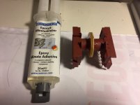
Here I have three samples of these Wurth's transformers. Obvioulsy they are designed to be fed by a PFC with about 380V=. With regular 310V= I would expect something between 150 and 200W. I will test them when I check the next prototypes are on the bench.
On the other hand I am sure that with less windings and higher switching frequencies short-term power of 400..600W should be doable with a single ETD39 core.
@voltwide
There are a lot of space for improvements in this construction, this is entry level model LLC with most probability for success as critical components (LLC controller + driver + MOS-FET) are integrated into single IC with optimized parameters to work in conjunction.
ST, NXP, OnSemi, Power Integration and other have own versions of LLC controllers with different functionality but more complex for integration and mostly with external switches ant that requires even more knowledge regarding drivers and MOS-FETs under HV operation which in general is quite complex.
Output power is not main concern, it can be leveled up as high as we have knowledge to build it, components it's self are not a problem. With SiC or GaN devices it is possible to build LLC converters up to hundreds of MHz with incredible high power density and efficiency.
This construction is just step-in ticket for LLC world")
There are a lot of space for improvements in this construction, this is entry level model LLC with most probability for success as critical components (LLC controller + driver + MOS-FET) are integrated into single IC with optimized parameters to work in conjunction.
ST, NXP, OnSemi, Power Integration and other have own versions of LLC controllers with different functionality but more complex for integration and mostly with external switches ant that requires even more knowledge regarding drivers and MOS-FETs under HV operation which in general is quite complex.
Output power is not main concern, it can be leveled up as high as we have knowledge to build it, components it's self are not a problem. With SiC or GaN devices it is possible to build LLC converters up to hundreds of MHz with incredible high power density and efficiency.
This construction is just step-in ticket for LLC world
Great!
Plese note few things, ceramic resistor need to be replaced with non-inductive type 2-3W, input filter choke (or Gretz) will be mounted last after you set working parameters under LV enviromen. Also check input voltage divider, there are only two resistor in series 180K + 180K.
If you need any help regarding this LLC do not hesitate to ask.
- Status
- This old topic is closed. If you want to reopen this topic, contact a moderator using the "Report Post" button.
- Home
- Amplifiers
- Power Supplies
- 200W LLC ZVS Power Supply with FSFR2100XS