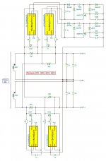
Regulation feedback monitor full output voltage of 56V and it is very tightly regulated, better then 10mV change of output voltage under load change from 0% to 100% and for specified range of input (mains) voltage.
Additional output rail (+/- 14V) are semi-regulated, will change up to +/-1V depending on load on main rail. Anyway, that rail is not critical, can be wound one more windings on secondary to get higher output voltage and feed that to some post-regulator if required.
Additional output rail (+/- 14V) are semi-regulated, will change up to +/-1V depending on load on main rail. Anyway, that rail is not critical, can be wound one more windings on secondary to get higher output voltage and feed that to some post-regulator if required.
Regulation feedback monitor full output voltage of 56V and it is very tightly regulated, better then 10mV change of output voltage under load change from 0% to 100% and for specified range of input (mains) voltage.
Then the question turns to be what is the regulation if only 1 rail is loaded.
")
PS: This PSU is slightly optimized for bridge type amplifiers like Bato MM and GND terminal is almost unused in such configuration. That is the reason why we chose to monitor full output rail, we need that voltage stable as much as possible.
Also I leave option on PCB for additional tweaking of power routes, one option for HB AMPs and second option for FB AMPs, for FB option I need to shorts circuit one point on PCB.
Also I leave option on PCB for additional tweaking of power routes, one option for HB AMPs and second option for FB AMPs, for FB option I need to shorts circuit one point on PCB.
Interesting, I'll check this one later!@voltwide
One solution by @Dragan100 for synchronous rectification based on TEA1892 single MOS-FET controller.
This can be used up to +/-36V, for higher voltage we din't find some simple solution yet.
@Pafi
Will check that, I expect very low change/asymmetry as main secondary have only 2 x 4 turns of Litz wire (130 x fi 0.09mm) and that small DC resistance will cause minor change on rail symmetry.
Thanks!
You will be surprised as this behaviour is not dependent only on DC resistance, but much more on leakage inductance between secondaries. And with 0 load on one rail also on parasitic capacitances.
@Pafi
I checked this asymmetry, at 2.5A load on one rail of 28V, other rail change around 0.5V.
Thanx!
Not bad. Do you mean 0.5V drop on the loaded rail and 0.5V increasment on the other, what is totally unloaded? Or there is some bleeder resistor on rails?
Does one need to use Litz wire to wind the HF transformer?
Can a multi paralleled wire be used, eg. 5cores of 0.3mm diam enamelled copper?
At what frequency does the transformer need to switch to make the change over from paralleled small diameter cores to Litz?
that does not answer any of the three questions I asked.
There is no universal and exact limit. But lets limit the discussion to this example, some hundred W of LLC, and integrated magnetics. Lets also assume we don't leave space on bobbin. At 50 kHz eddy current loss within the copper is about the same as resistive loss for diameter of 0.1mm. Any thicker wire not worth using.
But this is only true for the best possible winding arrangement. In 99 percent of cases somebody using induvidual wires parallel can not achieve an important requirement: each wire must see the same flux. Any imbalance induces an other circulating current along with wires, but in different direction in the paralleled wires. The loss caused by this can easily exceed all other copper losses.
The special braiding of litz wire ensures that no or very small flux difference arises between individual wires. This is the strong reason for using litz wire. Skin effect alone is ignorable, causes some % of loss increasement compared to solid wire. This is why most coax cables doesn't contain litze core.
Worth to understand how these losses/effects are created. (I will not explain it here, search for!) They are all a special form of eddy current.
- Skin effect is an eddy current created by flux induced by the current flowing on the individual wire. This is a small, axial current that flows in one direction in the middle, and other direction on the surface.
- Proximity effect is an eddy current created by flux induced by the current flowing on all wires near to each other. In case of high leakage transformer this is an incredible strong current circulating locally inside every piece of conductive material.
- Imbalance current is an eddy current created by flux asymmetry of multiple parallel wires, induced by current flowing on all wires. This current can also be higher than the original current.
Simple spiral twisting of enameled wires doesn't cancel skin effect (but who cares), but reduces imbalancing strongly, therefore real litze can be substituted this way for LLC transformers. But to avoid proximity effect the elemental wires must be really thin.
At what freq all of these effects are negligible for 0.3 mm wire regardless of the specific winding arrangement? At 1 kHz. Maybe even lower in case of higher power.
In case of separated series inductor the requirements are much lighter, the magnetic energy doesn't have to penetrate into the windings that much, so rougher wire can be used.
Thank you Pafi for that explanation. Do you think that copper losses in an integrated LLC-xformer can be reduced by hosing the litz wire to reduce proximity effect?
Sorry, I don't know what hosing mean. Especially in connection with litz wire. Could you explain it?
- Status
- This old topic is closed. If you want to reopen this topic, contact a moderator using the "Report Post" button.
- Home
- Amplifiers
- Power Supplies
- 200W LLC ZVS Power Supply with FSFR2100XS