I’ve heard these referred to as having different manufacturing “batches”
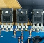
FET1-7, FET10, FET16-21 are all the same batch (they say 6G HU 722P)
FET8 is a different batch (G3 7T 832)
FET9, FET11-13, FET15 are another batch (RT XE 433P)
FET14 is another batch (82 6T 220P)
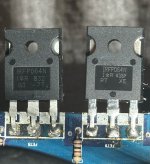
FET22-28 is another batch (6H D0 722P)
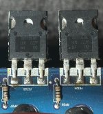
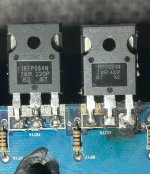
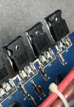
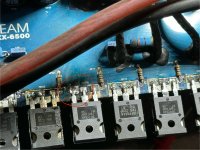
The images shown are where I got the numbers from
FET2 has continuity between gate and drain is this normal? It doesn’t change as charging a capacitor would
FET1-7, FET10, FET16-21 are all the same batch (they say 6G HU 722P)
FET8 is a different batch (G3 7T 832)
FET9, FET11-13, FET15 are another batch (RT XE 433P)
FET14 is another batch (82 6T 220P)
FET22-28 is another batch (6H D0 722P)
The images shown are where I got the numbers from
FET2 has continuity between gate and drain is this normal? It doesn’t change as charging a capacitor would
Attachments
Continuity is useless unless you're checking an incandescent lamp or a fuse.
If your meter is on ohms, what is the exact resistance reading displayed on the meter?
If on diode-check, what is the exact voltage reading displayed on the meter?
Does the gate resistor for that FET read the same resistance as the rest of the PS gate resistors?
If your meter is on ohms, what is the exact resistance reading displayed on the meter?
If on diode-check, what is the exact voltage reading displayed on the meter?
Does the gate resistor for that FET read the same resistance as the rest of the PS gate resistors?
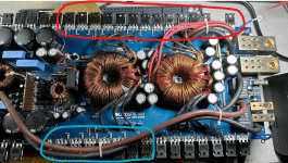
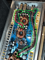
Circled are banks with same codes on the fets, red group have different date codes than blue, the non circled bank is a mix of codes
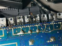
I added new solder to the bottom of all the power supply fets and top as needed, made sure there are no bridges
Did not add solder to the contacts that were pulled up or charred (pictures, hopefully able to be seen)
Amp does not turn on now as it tries to pull more than 10 amps (does not blow fuse) when remote wire is turned on, idles at about 2 amps with power LED on, protect led slightly lit, and the buzzing noise is back (i wonder if it’s a bad capacitor?)
Attachments
Not the gate resistor, I will do that
When I turn remote on (i have a switch to turn remote on/off) it jumps to 10+ amps then goes down to idle (I suspect maybe trying to charge the caps? It wont accept any power until remote is on)
It does not draw anything from what I see until remote is on (with main power already on)
When I turn remote on (i have a switch to turn remote on/off) it jumps to 10+ amps then goes down to idle (I suspect maybe trying to charge the caps? It wont accept any power until remote is on)
It does not draw anything from what I see until remote is on (with main power already on)
The bank of FETs with the defective FET will need to be replaced, preferably with matched parts. Since you probably won't order a fill 'stick' if FETs, order extras to have a better chance of getting enough from the same batch. Order from a reputable distributor.
Yes. The inrush is charging the caps.
Yes. The inrush is charging the caps.
More so to save about $20 but if you think I should just replace all of them I can do that (there is still that matched bank but for reliability I can replace that one too, making a complete fet replacement)
I don’t think they were heating evenly I think it was just 2 heating up
Also the middle contact on the top of the board, is that just for holding the fet? As in if the contact came off would I have to re-attach it?
I don’t think they were heating evenly I think it was just 2 heating up
Also the middle contact on the top of the board, is that just for holding the fet? As in if the contact came off would I have to re-attach it?
I'd think that $20 would be worth it if you have a better chance at getting matching FETs.
Are you referring to an unconnected solder pad? They are not critical. What's important is to solder to the pads that have traces connected to them. For intact pads/vias, properly soldering on one side will allow solder to flow to the other side of the board, if you are using good solder and enough heat.
Are you referring to an unconnected solder pad? They are not critical. What's important is to solder to the pads that have traces connected to them. For intact pads/vias, properly soldering on one side will allow solder to flow to the other side of the board, if you are using good solder and enough heat.
Make a jig of some sort to allow you to bend the leads precisely the same for every transistor. The results will look much better.
Lay the board in the heatsink and insert the FETs into the vias and get them all straight and flat. Then tack each one in, on one terminal to hold it in place/alignment. Remove the board and solder. If you'd prefer, you can solder all top pads before removing the board and soldering the bottom.
Lay the board in the heatsink and insert the FETs into the vias and get them all straight and flat. Then tack each one in, on one terminal to hold it in place/alignment. Remove the board and solder. If you'd prefer, you can solder all top pads before removing the board and soldering the bottom.
That's a good idea, I will keep that in mind when I get the new fets (ordered 32 off mouser, the extra 4 are backups)
So far about 3-4 contacts have come off the board as I removed the fets, I noticed they have all been "holder" fets and don't actually contact to anything, are these fine to leave off?
Btw, do you happen to know what gauge these sets of wires are? (Circled in green)
So far about 3-4 contacts have come off the board as I removed the fets, I noticed they have all been "holder" fets and don't actually contact to anything, are these fine to leave off?
Btw, do you happen to know what gauge these sets of wires are? (Circled in green)
Attachments
When laying out a 2-sided circuit board, when you lay out for a pad and via, the software places a pad on each side of the board. Sometimes there is a connection on only one side of the board. If so, that's all you need to solder to.
No clue on the wire. It doesn't appear to be burned. Why do you need to know the gauge?
No clue on the wire. It doesn't appear to be burned. Why do you need to know the gauge?
- Home
- General Interest
- Car Audio
- 2 Monoblock Class Ds Not Working, I'm Lost