Hello! I'm new to the forum and I'm hoping someone may be able to help me. I have been trying car audio amp repair but I'm lost at the moment.
I have 2 Monoblocks with different issues.
1. Concrete Audio 2k
Protect mode at 13v+ although rated up to 16v
At 12v, gain all the way down, no input, and with a speaker connected (I have tried a few different speakers and all do the same), starts normally then makes a loud pop every 3-4 seconds and flashes protect light
Does not happen with nothing connected (12v), audible click, power light and fans running, no protect
2. Soundstream XXX-6500D
Turns on with power LED and no protect, fans run, but no output to speaker terminals
Tried multiple speakers, tested with multimeter (any settings to try? I may not have tried correct setting), multiple RCAs, but only tested with 12v. This specific one has ratings at 13.5v, 14.4, and 16v but my other XXX-6500D has at 12v-16v.
Would 12v vs 13.5v cause this?
As of right now I would prefer to get the Soundstream working sooner than the Concrete Audio amp as I would like to install the Soundstream in my setup
I have a variable power supply that can go up to 30v and 3amps, a component tester, multimeter, and an oscilloscope but I am a bit confused on where to probe, what settings I should have, and where I should ground the probe or if I shouldn't use the ground lead.
Any help is appreciated and if there is anything someone would like me to send pictures of I can do so.
Sorry about that, thanks for letting me know
Cannot hear anything from either relay but they also may not be audible so not sure, any good ways to test?
LA5 has nothing (multimeter on acv)
I did notice a few more things though
FET1 middle leg snapped (previous solder snapped with the leg, no burn marks, more evidence of a shitty repair) and soldered it back together
FET2 and FET3 get warm to the touch while rest are cold
RP2 (next to FET2) has a burn line around it but still gives same resistance as the other RP resistors
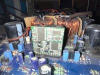
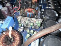
Buzzing sound coming from power supply section, sounds like between the transformers near those capacitors possibly (sounds like fan rattle or something so I unpugged the fan however sound persisted), when I played a test on it with gain very close to min. the sound would make a clicking noise (not like a relay would) and the amp would turn off (power LED still on and no protect)
Cannot hear anything from either relay but they also may not be audible so not sure, any good ways to test?
LA5 has nothing (multimeter on acv)
I did notice a few more things though
FET1 middle leg snapped (previous solder snapped with the leg, no burn marks, more evidence of a shitty repair) and soldered it back together
FET2 and FET3 get warm to the touch while rest are cold
RP2 (next to FET2) has a burn line around it but still gives same resistance as the other RP resistors
Buzzing sound coming from power supply section, sounds like between the transformers near those capacitors possibly (sounds like fan rattle or something so I unpugged the fan however sound persisted), when I played a test on it with gain very close to min. the sound would make a clicking noise (not like a relay would) and the amp would turn off (power LED still on and no protect)
OK. Back to the amp.
To see if the relays are being told to engage, measure the DCV across the diode DP5. What's the voltage?
With your scope set to DC coupling, 10v/div and 5us, do you see any sort of signal on either terminal of any of the inductors in the audio section?
^^^ with a signal driven into the amp. Also try at 2ms.
DP5 shows from -0.33v to -0.09v on multimeter, nothing the other way as expected, shows on the scope as positive voltage
Used a 40hz signal
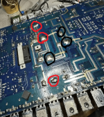
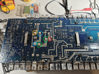
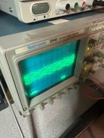
On the attached image I circled the points I probed
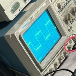
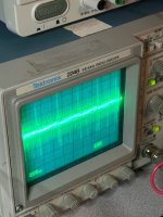
Red had shown a square wave (each line started with some frequency then faded to solid line, second picture)
Black had not shown anything some times and others I believe were just noise
I have a few questions though
The amp would draw 1amp at idle, then after I passed the signal through it would draw 2 amps at idle even after I stopped the signal, is that normal?
Is the buzzing noise anything to worry about?
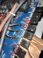
Finally, a few of the power supply fets have screwed up contacts, would this be a problem? (third picture)
(Fet15 and Fet11 first leg makes contact on top, not on bottom, Fet12 contact on top has been ripped off)
Used a 40hz signal
On the attached image I circled the points I probed
Red had shown a square wave (each line started with some frequency then faded to solid line, second picture)
Black had not shown anything some times and others I believe were just noise
I have a few questions though
The amp would draw 1amp at idle, then after I passed the signal through it would draw 2 amps at idle even after I stopped the signal, is that normal?
Is the buzzing noise anything to worry about?
Finally, a few of the power supply fets have screwed up contacts, would this be a problem? (third picture)
(Fet15 and Fet11 first leg makes contact on top, not on bottom, Fet12 contact on top has been ripped off)
Attachments
DP5, DCV on your multimeter with the probes directly across the diode?
The added current draw could be normal if the difference is the output stage oscillating (or not).
I doubt the buzzing is a problem.
The combination of the dirt and soot on the board and the angle/focus of the photo, I can't tell much about the solder connections. Clean it all up with acetone and a toothbrush and repost.
Between the glare and the low resolution, I can't tell anything in the first photo.
DP5, probes directly across the diode yes
Testing the amp today I realized that when the amp goes from 1amp at idle to 2amps, the protect LED comes on so I have actually been testing with protect on I believe
I'm honestly glad the images had an issue with compression because I realized I had probed the wrong points and I now have different readings
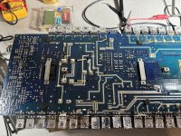
I hope these new images are easier to read and better quality
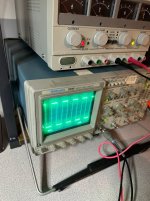
I color coded where I probed and what the readings were, these are coils LA3, 4, and 5
Yellow showed a large square wave
Blue showed a smaller square wave
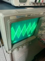
Green showed a triangular wave
Red showed a noisy signal that changes when I increased/decreased the gain
I will try to get a better photo of the mosfet connections when I clean up the board
Testing the amp today I realized that when the amp goes from 1amp at idle to 2amps, the protect LED comes on so I have actually been testing with protect on I believe
I'm honestly glad the images had an issue with compression because I realized I had probed the wrong points and I now have different readings
I hope these new images are easier to read and better quality
I color coded where I probed and what the readings were, these are coils LA3, 4, and 5
Yellow showed a large square wave
Blue showed a smaller square wave
Green showed a triangular wave
Red showed a noisy signal that changes when I increased/decreased the gain
I will try to get a better photo of the mosfet connections when I clean up the board
Attachments
Confirm that you read 0 ohms between the drain of M9 and the point in blue.
Also confirm that you read 0 ohms between the source leg of M10 and the point in blue.
With your meter connected across those two points, move all of the inductors to see if the connection is ever broken (goes above 0 ohms).
What waveform do you see on those two FET terminals when the amp is idling?
I read 0 ohms with both connections, moving the inductors did nothing
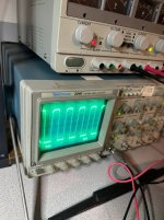
Picture one is M9 drain
Picture two is M10 source
This is at idle but after protect mode turned on (engages after about 5 seconds or when input is put through)
I probed M9 drain before the protect mode turned on for a second and it looked like what red showed in my previous post
Picture one is M9 drain
Picture two is M10 source
This is at idle but after protect mode turned on (engages after about 5 seconds or when input is put through)
I probed M9 drain before the protect mode turned on for a second and it looked like what red showed in my previous post
Attachments
Does it go into protect (earlier than the normal 5 seconds) by simply having the RCA cables connected (no signal).
Monitoring the inputs to the PS driver board, you see any that are changing just prior to or when the amp goes into protect?
Do you see DC voltage increasing across the speaker terminals just before it goes into protect?
Monitoring the inputs to the PS driver board, you see any that are changing just prior to or when the amp goes into protect?
Do you see DC voltage increasing across the speaker terminals just before it goes into protect?
It did in the previous post but now it has to have some signal and gain turned up a bit, and as I turn the gain up its nothing until it shows anything and goes into protect (powered on for 5 mins fine with only rcas and nothing)
The driver board is the green one I recall? I tested pin 1 of it and nothing showed
Nothing on speaker output before, switching to, or after protect
Tried probing M9 drain again, noticed every 4 seconds it would flash a square wave that turns to a sine wave or something, it was pretty odd
The driver board is the green one I recall? I tested pin 1 of it and nothing showed
Nothing on speaker output before, switching to, or after protect
Tried probing M9 drain again, noticed every 4 seconds it would flash a square wave that turns to a sine wave or something, it was pretty odd
- Home
- General Interest
- Car Audio
- 2 Monoblock Class Ds Not Working, I'm Lost