...and I went on with several adjustments of the shut down, with an larger triangle signal (now +/-500mV), new adjusted frequency compensation of the power amp.. And I added an OP amp input stage, which allows me to get low offset (1.5mV without adjustment), high PSRR, symetrical input and additional feedback for lower distorsion.
In the following postings some results.
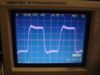
Let's start where I stopped last time. Transient response.
Here a screen shot when powering a 10kHz rectangular signal with 200Wrms into 1.9 Ohms.
I experimented with several adjustments and here is the trade off, which seems most resonable for me.
I used a 10:1 probe, so the scale is 10V/grid.
In the following postings some results.
Let's start where I stopped last time. Transient response.
Here a screen shot when powering a 10kHz rectangular signal with 200Wrms into 1.9 Ohms.
I experimented with several adjustments and here is the trade off, which seems most resonable for me.
I used a 10:1 probe, so the scale is 10V/grid.
Attachments
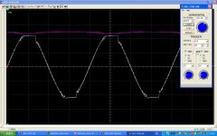
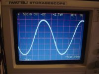
The clipping behavior is slightly suffering from stronger overall feedback, but still not bad.
The strongest power supply, which I have on hand, is sagging at 500W fro,+/-55V to +/-48V.
Clipping happens at 500Wrms into 1.9 Ohms.
So in bridged configuration you will get 1kWrms into 4 Ohms, if you have a strong enough PSU.
The red trace is the positive rail.
The white trace is the clipped output signal.
You can see roughly 4V difference between rail and clipped output. These 4V are lost in the current sensings resistors, the switches, the filter choke and wiring (still some room for improvement).
I used 10:1 probes. So the scales are 20V/grid.
Attachments
Some distorsion measurements. 1kHz signal and harmonics measured up to 10th harmonic.
In order to avoid a boring posting, I am just pointing out the dominant part of the distorsion spectrum.
8 Ohms / 1W:
k2 = 0.0058%
1.9 Ohms / 4.2W:
k2 = 0.0079
1.9 Ohms / 100W:
k2= 0.03%
k3= 0.009%
1.9 Ohms / 400W:
k2= 0.073%
k3= 0.021%
k5= 0.009%
k6= 0.009%
In order to avoid a boring posting, I am just pointing out the dominant part of the distorsion spectrum.
8 Ohms / 1W:
k2 = 0.0058%
1.9 Ohms / 4.2W:
k2 = 0.0079
1.9 Ohms / 100W:
k2= 0.03%
k3= 0.009%
1.9 Ohms / 400W:
k2= 0.073%
k3= 0.021%
k5= 0.009%
k6= 0.009%
So far the results are fine.
I should be happy.
But.... Ughhhh, what's this?!!!
...may be I should now really think about making a proper PCB..
P.S:
I agree. Especially for class D a proper PCB is helpful, but doing the fundamental design is so much more fun.
P.P.S:
I needed to do this fundamental learning exercises.
Without this proto, I would have missed many important basics and wasted several time consuming and expensive PCB design loops.
P.P.P.S.
I cannot promise, when I will post an updated schematic.
But it is on my ToDoList.
P.P.P.P.S.
...the same for listening tests...
Attachments
Distortion is surprisingly low considering that your source snubbers introduce variable dead time and propagation delay. How much feedback are you using at 1Khz?
What are you using to filter carrier residuals and measure THD? How does THD increase at 2Khz and 4Khz? 6dB/oct?
Anyway, this is good news to me because I have a new version of my coupled-inductor magnetic snubber for +/-200V class D that achieves much less copper and core losses, like only 25ºC temperature rise for 2500W output at 50Khz Since magnetic snubbers impose variable delays, your results imply that I could get low THD with my approach too and enough feedback I have even better cores in the way that should theoretically allow to get similar losses at 100Khz, so cool full-range 250Khz operation may be practical now.
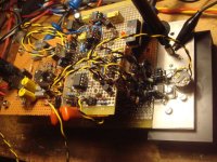
BTW: This stripboard with ground plane is funny
What are you using to filter carrier residuals and measure THD? How does THD increase at 2Khz and 4Khz? 6dB/oct?
Anyway, this is good news to me because I have a new version of my coupled-inductor magnetic snubber for +/-200V class D that achieves much less copper and core losses, like only 25ºC temperature rise for 2500W output at 50Khz
Since magnetic snubbers impose variable delays, your results imply that I could get low THD with my approach too and enough feedback I have even better cores in the way that should theoretically allow to get similar losses at 100Khz, so cool full-range 250Khz operation may be practical now.BTW: This stripboard with ground plane is funny
...once upon a time....
http://www.diyaudio.com/forums/showthread.php?s=&threadid=83899&highlight=
Claus Larsen told me that 10ns are King Kong's feet.
And also my younger simulations confirmed this.
So I spend some love to this adjustment. In this regard really everybody has to find his individual limit what he can handle.
The power stage offers roughly 28db feedback over the entire audio range. The additional OP amp stage is adding another 33db at 1kHz, with mostly integrating characteristic.
But please note the additional 33db did not reduce the distorsions by factor 45, but roughly by factor 5 only.
No measurement at higher frequencies so far, but may be I will go on to measure this baby at John's place. Wasn't there a audio precision and tons of more fun stuff?
To avoid irritating my measurement sound card I using a passive 100 Ohms / 100nF low pass.
I am attaching the updated schematic.
Please note my triangle is +/-340mV.
Not +/-500mV as stated earlier, with +/-500mV the k2 distorsions increased roughly by factor 3, while the other harmonics remained similar.
Wishing you good success with your 2.5kW monster!
Please keep us updated.
Attachments
Today I started to use this wild proto in my HiFi system.
Even without any speaker relay, the turn on 'pop' is unexpected low. The turn off is just a silent 'tick'. Nice.
The listening comparison is going vs the analog Rookie.
Please remember the analog Rookie amp ended up in two designs. A MosFet and a bipolar version. Originally I preferred the bipolar, it was more alive. Other listeners preferred the MosFet version, because they felt the bipolar version to be slightly intrusive. In the mean time we also went on with listening tests to different tweeters. And found my new love! Ribbons. In combination with ribbons also the very decent MosFet Rookie turned really alive. And in this combination I cannot say anymore which Rookie I prefer, they are both lovely in their own way.
My new class D proto again has its own character, it is something inbetween, but not exactly inbetween...
I am listening to it now since two hours and still there is no annoying effect. It plays quite relaxed on the same level as both Rookies. So I will keep the proto in my system and go on with listening. ... going to gain more experience in the musical pros & cons of my proto...
Overall ...aloha.... class D seems to be by far more audiophile than what I was assuming two years ago....
Amplifiers designed in the way we do it are too perfect to introduce any noticeable change in the signal. You would probably not be able to tell which one of the three you are listening to in a proper blind test.
Speakers are much more challenging. In amplifiers you only have to care about one-dimensional waveform integrity, there are no delayed copies of the signal to deal with, no energy storage at certain frequencies, etc... In speakers, the pressure waveform radiated in every direcction by every driver over time matters, and the relationship between the stuff radiated by each driver is even more critical because it defines directivity, lobing and room interaction (the sense of width and depth). Every small change in speaker radiation characteristics produces potentially big changes in what you hear. Try to guess what speaker are you listening to in a blind test and you will hardly fail.
Speakers are much more challenging. In amplifiers you only have to care about one-dimensional waveform integrity, there are no delayed copies of the signal to deal with, no energy storage at certain frequencies, etc... In speakers, the pressure waveform radiated in every direcction by every driver over time matters, and the relationship between the stuff radiated by each driver is even more critical because it defines directivity, lobing and room interaction (the sense of width and depth). Every small change in speaker radiation characteristics produces potentially big changes in what you hear. Try to guess what speaker are you listening to in a blind test and you will hardly fail.
...if you do not hear any difference between your amps, then I would tend to say that your speakers are the dominant bottleneck of your system.
I agree that the speakers are usually much more coloring the sound than the amp. But this does not mean that amps are all the same.
And perfection?! May be your amps are close to perfection, but my proto still has multiple design short comings. At least my way to generate the triangle and my PCB are school book examples of how not to do it.
Ok, ok... it measures fine and sounds OK.... but perfection??? !!
I would rather say
"perfection" was more a compliment to your work than to mine. By "perfection" I mean a ridiculously small difference between input and output waveforms. Anyway, speakers, room acoustics and recordings are the never ending bottleneck. The more research I do about loudspeakers and acoustics, the more perfect amplifiers become from my point of view. I wish speakers and the own air were at least as linear as the worst of our amplifiers, but they are far worse.
Ooohps, flowers from Eva ...nice lady.. I like this day 
Yes, speakers are really a key factor. My current speaker playground:
http://www.diyaudio.com/forums/showthread.php?s=&threadid=101377
...and in the meantime I am really wondering why ribbons are not more popular...i.e. R1L is worth listening and not expensive... http://www.partsexpress.com/catalog/pdf/195pec08.pdf
Regarding my class D amp I am considering the IRS20955. There is a unscientific concern in my stomach regarding the long propagation delay.
Currently the overall propagation delay from comparator input to half bridge output is roughly 120ns.
Comparator: 20ns
Level shifter: 40ns
MosFet driver: 30ns
di/dt regulation plateau: 50ns
ugs-sloping: 10ns
So the IRS20955 level shifting would increase the delay by 50ns. On the other hand then I could use a simple discrete buffer with some Zetex bipolars instead of the UC3710 MosFet drivers. This would save around 20ns.
Another possibility to keep propoagation delay short is the comparator. The LT1016 instead of the LM160 could save me another 10ns.
So I could get even with IRS20955 an overall delay around 140ns-150ns.
...hm, this is temptation for a low-component-count-junky... ...even the shut downs integrated...
How much propagation delay "jitter" from comparator output to power switching node is producing your current setup? I think that this is what matters (and not propagation delay itself), and I don't know if you are going to improve this with IRS20955. The most significant change would be part count reduction.
Concerning ribbon tweeters, I bet that what you love of them is the narrow vertical directivity (probably without being aware of the complex baffle and room interactions behind). This may end up leading you to experiment with trebble and midrange horns and then you may discover the world of directivity and well-defined reflection-less sound in rooms (then you just avoid direct radiators).
Concerning ribbon tweeters, I bet that what you love of them is the narrow vertical directivity (probably without being aware of the complex baffle and room interactions behind). This may end up leading you to experiment with trebble and midrange horns and then you may discover the world of directivity and well-defined reflection-less sound in rooms
(then you just avoid direct radiators).Hi Eva,
..yes the di/dt limiter adds delay variations depending on load.
But if you allow 500A/us or more then this variation is not harmful.
Finally it is all about proper adjustment of the switching events and choice of inductive ripple current....
I spend 90% percent of my learning time on the power stage and in the mean time I learned more or less to handle it. I think the low distorsions are mostly related to my adjustment of the power stage.
...sorry, I cannot send further screen shots, because I am traveling.... and also after that, not much chances for playing...
Directional behavior of tweeters is definitely a point that I do not appreciate, because I do not want to optimze the sound in just one sweet spot.
And that's a nice thing with the R1L. It is a circular design with phase plug. So it also sends signals to the well reflecting ceiling and floor. From my perception it is not very directional, but I do not have measurements.
Linear variable delays don't seem to be harmful which is good news for anybody using magnetic snubbers only the abrupt delay change from dead time is.
Sorry, I was expecting your ribbon to be of the flat and vertical type. Multiple-path reflected sound is the opposite of dynamics and imaging, but with direct radiators the fault is always there, in every room and system, and you get used to it and you learn to live with it, without any chance to taste the absence of reflections
only the abrupt delay change from dead time is.Sorry, I was expecting your ribbon to be of the flat and vertical type. Multiple-path reflected sound is the opposite of dynamics and imaging, but with direct radiators the fault is always there, in every room and system, and you get used to it and you learn to live with it, without any chance to taste the absence of reflections
fredos said:....Have you Try TC4429 from Alpha? They are pretty faster than the 3710! ...
Fredos
This night I found time and muse to look for the TC4429 data sheet.
And now I am wondering about your statement that they would be faster than the UC3710.
Typical rise and fall times are 25ns for both drivers, but the propagation time of UC3710 is just 35ns vs TC4429 with 55ns...
- Status
- This old topic is closed. If you want to reopen this topic, contact a moderator using the "Report Post" button.
- Home
- Amplifiers
- Class D
- 1kW Gen2