Aloha ...nice pictures everywhere...
OK, I'll also send some pictures.
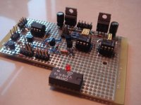
I kicked my lazy xxxx during the weekend and converted the naked half bridge to something like a class D amp.
Triangle, LM160 comparator, discrete level shifter, multiple shut down functions.
As always a breadboard not as sexy as most a proper PCBs , but Choco-handmade
OK, I'll also send some pictures.
I kicked my lazy xxxx during the weekend and converted the naked half bridge to something like a class D amp.
Triangle, LM160 comparator, discrete level shifter, multiple shut down functions.
As always a breadboard not as sexy as most a proper PCBs , but Choco-handmade
Attachments
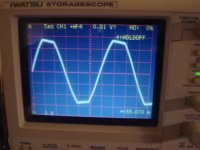
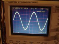
...a short look to the clipping behavior.
I am supplying all auxiliaries from my small flyback, so all supplies remain stable no matter how much clipping you drive. Nice to get blameless clipping bahvior. The capacitive couplings of my flyback are small (15pF), so easy fast floating for the high side supply is no issue.
Here a screen shot in low frequency clipping with 2.5Ohms load.
Ok, Ok, for my first examinations I am using a weak power supply which is dropping from +/-50V down to +/-28V...
Please note I used a 1:10 probe, so we have 10V/grid.
Attachments
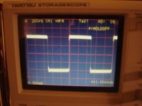
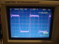
My output filter is 5uH, 3uF and a damper with 10uF/1.7 Ohms.
Feedback is splitted partially from halfbridge and partially behind the filter, this helps to optimize the transient response.
Here a screen shot of running a 1kHz rectangular signal into 2.5 Ohms load.
Probe 1:10 ==> 5V Grid
Feedback is splitted partially from halfbridge and partially behind the filter, this helps to optimize the transient response.
Here a screen shot of running a 1kHz rectangular signal into 2.5 Ohms load.
Probe 1:10 ==> 5V Grid
Attachments
ChocoHolic:
Post like yours are what makes diyAudio such an incredible forum.
Discussing candidly your design merits and tradeoffs, providing full schematics, and a running project history....
Thanks for your efforts, and congratulations on a design which shows lots of promise....
Your square wave test shows a very well behaved circuit. Perhaps I would only use a faster timebase to better inspect the edges.
Hi Eva,
yes I have several reasons to use such a low L.
1. How about driving ESL speakers? Most class D output filters will go to dramatic mistuning (and quite low roll off frequency), when loaded with several uF capacitive load. A design with low L and large C can serve such loads much better.
2. Distorsions.
3. Hardswitching only during really high power passages.
4. Low output impedance even at high frequencies.
With roughly +/- 8A filter the ripple half bridge will almost always operate in inductive load condition.
Means I can systematically avoid the dead time distorsions during 99% of my listening time.
The ripple is still low enough to keep losses uncritical.
Overall idle power consumption is 6W.
Whereof I know that already 2x1W are the snubbers, may be 0.5W.. 1W in my flyback, roughly 1W in the output filter...
Of course you have to make sure that your rail e-caps are OK for the resulting effective cap ripple current of roughly 3.3Arms, but that's no problem. I am using 2x8x100uF nonames. No self heating visible. Also the specs for low cost series of global brands allow 500mA..600mA for a 100uF/100V cap (if I remember right...).
My filter choke is a gapped ferrite design with HF litz wire. With a metal powder core you might run into issues for this filter design. At 320kHz the losses of metal powder would allow just very low flux densities.
Hi Fernando,
thanks. It's nice to hear that you appreciate my postings.
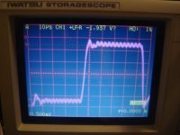
...ah well, of course I had a look with faster time base...
And of course also with higher frequency. Frankly speaking my previos post was more for 'marketing' and making people cuorios.
If you look at the next screen shot with 20us time base and a 10kHz / 24Vpp square wave, then it becomes obvious that these results are good, but not perfect.
yes I have several reasons to use such a low L.
1. How about driving ESL speakers? Most class D output filters will go to dramatic mistuning (and quite low roll off frequency), when loaded with several uF capacitive load. A design with low L and large C can serve such loads much better.
2. Distorsions.
3. Hardswitching only during really high power passages.
4. Low output impedance even at high frequencies.
With roughly +/- 8A filter the ripple half bridge will almost always operate in inductive load condition.
Means I can systematically avoid the dead time distorsions during 99% of my listening time.
The ripple is still low enough to keep losses uncritical.
Overall idle power consumption is 6W.
Whereof I know that already 2x1W are the snubbers, may be 0.5W.. 1W in my flyback, roughly 1W in the output filter...
Of course you have to make sure that your rail e-caps are OK for the resulting effective cap ripple current of roughly 3.3Arms, but that's no problem. I am using 2x8x100uF nonames. No self heating visible. Also the specs for low cost series of global brands allow 500mA..600mA for a 100uF/100V cap (if I remember right...).
My filter choke is a gapped ferrite design with HF litz wire. With a metal powder core you might run into issues for this filter design. At 320kHz the losses of metal powder would allow just very low flux densities.
Hi Fernando,
thanks. It's nice to hear that you appreciate my postings.
...ah well, of course I had a look with faster time base...
And of course also with higher frequency. Frankly speaking my previos post was more for 'marketing' and making people cuorios.
If you look at the next screen shot with 20us time base and a 10kHz / 24Vpp square wave, then it becomes obvious that these results are good, but not perfect.
Attachments
...and here the schematic without shut down circuits. In fact I am using the NI IN pins for shut down functions....
So this schematic is showing just the core of the amp.
I am pleased about the propagation delay of just 120ns from comparator input to halfbridhe output. On the other hand it turned out that this is only helpful for the feedback from HB and this feedback is limited much ealier by the requirement that the resulting dv/dt at in1 must be less than the dv/dt from the triangle at in2 of the LM160. From simulation it looks like you can get almost identical results no matter if your over all propagation delay is 100ns or 300ns. So the typical integrated halfbridge drivers would probably be OK as well.
For the feedback from behind the filter you can neglect the influence of some ns propagation delay, here the LC is dominant.
In fact the layout is always a concern in class D and nobody really wants to see my messy breadboard. But I will go on with some optimizations and tests, before designing a nice PCB.
Attachments
ChocoHolic said:
Hi Fernando,
thanks. It's nice to hear that you appreciate my postings.
...ah well, of course I had a look with faster time base...
And of course also with higher frequency. Frankly speaking my previos post was more for 'marketing' and making people cuorios.
If you look at the next screen shot with 20us time base and a 10kHz / 24Vpp square wave, then it becomes obvious that these results are good, but not perfect.
I'm still very impressed with the squarewave performance.
I can't read the scope photo very well, but it seems that the amp's slew rate is ~ 24/5E-06 or roughly 4.8 volts per microsecond. Not bad, not bad at all!
Also the overshoot indicates minimal ringing, it settles within 2 or 3 switching cycles, very close to critical damping. NICE! You got it very close to optimal.
However if you have the time and are very perfectionist, you could try some snubbering at the output to dampen it further. Don't know if this would provide any sonic improvement, perhaps only in percussive sounds.
It is around 6V/us.
I can adjust the response speed and overshoot by the feedback network. See the 220pF cap....
Theoretically a more complex PID feedback should allow more improvements. But for first step this simple solution is not bad.
More details and optimizations to come, but probably not before Christmas. May be around New Year...
Attachments
fredos said:Hi Choco
Your 1N4148 in the bootstrap supply of the hight side is not blow?110V of bootstrapping involve smoke in your project!
Fredos
...to fast!
...you posted to fast. Right?The 1N4148 does only see the 12V of the high side driver supply.
Higher voltage is seen only across the BAV21 (fast 250V type).
OK I catch your level shifter now...I saw the junction at 4.7V zener and 1N4148 stay at 55V and 55V+12V when shifting..Nice idea! This do not reflect spike at output 1 of LM360 when switching (trought the 2N5551)? Have you Try TC4429 from Alpha? They are pretty faster than the 3710! And another question...Not better to damp power supply trought +/-55V than to damp it trought ground with your 2uf? I saw that my design of skipping error amplifier have seduct you...That work very well! It's easy to implement a current sense trought the inductor current ( with differential amplifier ) and feed back current image (in phase) to the triangle wave...More current : more triangle wave amplitude = less gain and better stability for amplifier to handle short circuit...Dont forget hight pass filter to only recover carrier current on coil...
Fredos
Fredos
fredos said:It's easy to implement a current sense trought the inductor current ( with differential amplifier ) and feed back current image (in phase) to the triangle wave...More current : more triangle wave amplitude = less gain and better stability for amplifier to handle short circuit...Dont forget hight pass filter to only recover carrier current on coil...
Fredos
Now it seems you have taken seriously what i once said to use inductor current image for short-circuit sensing.........
This way you can eliminate lossy resistors to sense current .........One can also take the image of zobel current to further ease the situation.....Kanwar
fredos said:OK I catch your level shifter now...I saw the junction at 4.7V zener and 1N4148 stay at 55V and 55V+12V when shifting..Nice idea! This do not reflect spike at output 1 of LM360 when switching (trought the 2N5551)? Have you Try TC4429 from Alpha? They are pretty faster than the 3710! And another question...Not better to damp power supply trought +/-55V than to damp it trought ground with your 2uf? I saw that my design of skipping error amplifier have seduct you...That work very well! It's easy to implement a current sense trought the inductor current ( with differential amplifier ) and feed back current image (in phase) to the triangle wave...More current : more triangle wave amplitude = less gain and better stability for amplifier to handle short circuit...Dont forget hight pass filter to only recover carrier current on coil...
Fredos
TC4429... might be interesting, but in fact the 100ns between comp out and half bridge are already faster than you really need. At least regarding loop stability and transient response. In which other points would I get benefits from reducing propagation delay further? ...would be really interessting to understand the opinion of our ears on such improvements! Do you have sonically compared diffrent propagation delays in identically setups?
Seduced by your design? Ooohps sorry to say: I got this inspiration from the self oscilating designs
..and frankly speaking I like it, but I am planning to add an OP amp circuit in order to get an symmetrical input for easy bridging. And at the same time I want use the additional gain for an additional feedback loop. Ending up in a quad staggered feedback system, which should allow to keep good transient response, reduce distorsions, derive low DC offset and beam LF PSRR to the moon. So far the theory....
Cap from +55V to -55V: I agree the critical path for HF ringing is from + to - . GND connection is less important. The schematic is correct, but misleading. In my layout I have the ceramic caps directly between the rails like series connection with center tap.
Loop inductance is completely dominated by my di/dt limiter. If I skip the metal powder torroids the parasitic inductance seems to be very low. At least the resonance (almost invisible due to drain source snubbering) is 120MHz.
My Over Current Protection is a traditional straight forward 2-transistor-latch, see the attached PDF. Sensing by two simple shunts. Transfer of the shut down information towards the MosFet drivers through optocoupler (the low side driver can of course easily be accessed without optocoupler...).
In the moment my OCP is adjusted for fast acting.
The inductive part of the shunts is bringing a D characteristic for the voltage signal and fast peak value storage is memorizing this info immediately... May be I will slow down the acting by putting a resistor in series with each 1N4148.
Attachments
- Status
- This old topic is closed. If you want to reopen this topic, contact a moderator using the "Report Post" button.
- Home
- Amplifiers
- Class D
- 1kW Gen2