A picture is needed, at least for the slower ones like me. I suspect things can be managed more simply than you think.
Draw it, annotate, fax to your computer (if you don't have a scanner or a Kinko office), post it.
About that trace Mark posted with the flat 20-25kHz response. Either it is the world's greatest woofer ever made or could it be the mic calibration curve? What are we looking at?
Ben
This is for Ben and whomever. Some more of more terrific MS Paint art.

So, you're gonna try to take away my blue ribbon, Mark Out of my cold, dead hands!!!

So I've still got work to do.
Bach On
Nope the ribbon is yours.
The mistake was software related.
You used the latest version of REW. I opened the file in an older version. From there the trouble began.
You did do a very realistic measurement of your system.
It is working very well.
The only work I would suggest is to ask REW to do an impedance curve. Wideband. We can then verify your port tuning.
That may make you more work.
You can get a db or so better results with getting the tuning right. But to make you feel better, you have already stated seeing diminished cone travel at 16 Hertz. So I think you are pretty close.
This is for Ben and whomever. Some more of more terrific MS Paint art.
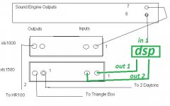
Is that the final signal path?
This is how mine would look, just for funsies.
Attachments
Is that the final signal path?
This is how mine would look, just for funsies.
Ben,
You're missing one thing. I limitation of the XLS1000, XLS1500, etc. is that when either Lowpass or Highpass is used, input channel 2 goes offline. (I did not know this when I bought them.) So anything plugged into input channel 2 on the XLS models we have is ignored. The newer XLS models no longer suffer from that problem. But we don't have the newer models.
Your drawing has a one of the outputs from the Rolls going to Input 2 on the XLS1500. That would accomplish nothing because that input goes offline in Crossover mode. If the Rolls preamp is used, it will only be used for the cable from Output 8 of the Sound Engine and Input 1 of the XLS1500. The amp goes into a modified Bridge mode so that both Outputs only carry the amplified signal from Input 1. But both volume controls work independently on the two outputs. Both of our low bass speakers will be driven by this amp.
So the idea of adding some equalization circuit in the input to the XLS1500 amp means that a signal tailored for the SI HT18 might help that box. But it would also effect the twin Dayton Box - and it might or might not be better.
The only workaround for this is to buy another XLS amp for the box with the two Dayton Drivers. And I just don't have the budget for that..
I know that is confusing. It doesn't work like it should. But I'm certain of my facts. The instructions in the manual are confusing and were modified to make them a little more clear. I've confirmed these facts with the vendor - who confirmed it with Crown. Customers bought the same ones we have and complained about this limitation. So Crown changed the design in the newest models by adding another DSP chip to process both Inputs independently like it should have done all along. The price on the old models is now about $50 less than the new ones. I bought four XLS1000s in May for $299 each. They now cost $249 each. And no equitable trade-in is offered. I'd take a beating selling the old amps and buying the new ones.
Plus, I don't have time to do it.
Bach On
* The confusing limitation I've just been describing is not a factor when the Crossover circuitry of the older XLS models is by-passed. I don't need the crossover circuits for sound engine outputs for the manuals. The Allen HC12s have a built-in 3 way crossover system. So the three XLS1000 amps that power these speakers work fine in typical stereo mode. If I by-passed the crossover on the xls1500, I could do the circuit like you drew it. But I'd need a crossover for each of the bass signals.
Last edited:

Originally Posted by mwmkravchenko
What I would do is make a high pass filter. Cut all the stuff higher than the signal that we want to boost. Then we can use the gain of the Rolls unit to level everything off.
Sure thing. Of course you will need to take account of whatever LPF Bach On selects in the calcs etc. Otherwise !
@ Master ZD
You have made be brush up on the correct formula for calculating the passive EQ should we need it. Thanks! Old dog can learn new tricks.
The same thing happens to me from time to time with stuff. All good though
I had a nice spreadsheet hiding in among the files
That's not the only thing that's been hiding, re PM
@ Bach On
Re the limitation of the XLS1000, XLS1500 when either Lowpass or Highpass is used, input channel 2 goes offline.
If Mark designs that boost & filter to include a 18-24Db Oct HP & with a LP @ your noted 96Hz, you will be able to use Both channels independently, as the above circuit will just feed the SI HT18 driver
Mark,But what I have seen is that the SPL level of the harmonic can be influenced by the distance of the reflection points if there are correlations between the harmonic wavelength and the distance away from a reflective surface.
Here is a simple example. Put a cabinet under test 8 feet away from a reflective surface. Play a 32 hertz tone and look at the height of the harmonic at 64 hertz. That would be the first harmonic right? 8 feet is also roughly the half wavelength of the first harmonic. When these things line up they can influence the measurement outcome.
Your example is correct, but the 64 Hz harmonic of 32 Hz is called the Second harmonic. All even order harmonics are octaves of the fundamental, and thus are always musical, while the odd order harmonics (96 Hz, 160 Hz etc.) can/will/may change the sound of the musical composition.
Art
View attachment 493535
Have at er boys!
I have seen similar results on another site that I trust. It is an inexpensive driver with a lot of throw. You can't have everything.
But it will indeed sound impressive.
Thanks for distortion trace but oddly high and messy. 10% (which is 20 dB below the full output) wouldn't be unexpected for this system, short of over-load. But seeing so much in the chart more raises questions about the test method or perhaps the speaker drive signal.
Easiest on the eye and brain to stick with 1/12 smoothing (the "Goldilocks" level) for all displays. Likewise, meaningful to see THD, 2nd, 3rd, and maybe 4th can still be seen clearly; anything more too hard to handle.
Honestly, time to see if the input signal to the final amp is clean and flat. All you do is turn off the Crown and then connect the input cable to whatever your mic (or mic box) is connected to. That's it.
Ben
Last edited:
Sure thing. Of course you will need to take account of whatever LPF Bach On selects in the calcs etc. Otherwise !
@ Bach On
Re the limitation of the XLS1000, XLS1500 when either Lowpass or Highpass is used, input channel 2 goes offline.
If Mark designs that boost & filter to include a 18-24Db Oct HP & with a LP @ your noted 96Hz, you will be able to use Both channels independently, as the above circuit will just feed the SI HT18 driver
First, sorry I aimed that long winded response to Ben instead of you, Zero D.
I understand what you're saying. I'm pretty sure I can do simple circuit work like changing the caps in that Rolls preamp. But too many components and my right brain gets really confused. So I admit to some reservations. And did I mention that this is going to be going live real soon?
Bach On
Last edited:
Honestly, time to see if the input signal to the final amp is clean and flat. All you do is turn off the Crown and then connect the input cable to whatever your mic (or mic box) is connected to. That's it.
Ben
So I should use a volt meter to measure the output coming out of the Rolls box?
The problem is that it has been taken apart and is awaiting brain surgery.
I plan to measure the voltage at the subwoofers this week with a volt meter. We're pulling all the speakers out of the speaker chamber and putting up insulation and sheet rock tonight. Most of the speakers will go back into the chamber on Sat. morning - including the two bass boxes. So I have this week until Sat. AM to do whatever carpentry work is needed for the triangular box. I really don't think I can get all the speakers in their final position until those big Bourdon pipes are removed on the 27th. And we won't have a clear path for testing sound into the Sanctuary until they are gone.
That's when I'll get a first hearing on how well the new bass boxes will project out to the pews.
Bach On
View attachment 493535
Have at er boys!
I have seen similar results on another site that I trust. It is an inexpensive driver with a lot of throw. You can't have everything.
But it will indeed sound impressive.
Mark - I will freely admit that I haven't the foggiest idea what this graph is indicating.
But I like it when you tell me it will sound impressive.
Bach On
The AC voltmeter method was the simplest way to get a rough picture. You put in a reference tone in (say, 100 Hz) and set the volume control for 2.5 volts. Then you put in 20 Hz and see if you need to crank up or down to get 2.5 volts.So I should use a volt meter to measure the output coming out of the Rolls box?
The best by far and easiest thing to do is to connect REW to the terminals of each of your speakers or to any intermediate point in the path where things might go astray. Couldn't be simpler once you have the cables with the right plugs or jacks.
For the speakers, where the rubber meets the road, you can buy or make an ordinary audio cable with bare wires sticking off the end. Taking care to keep computer-ground connected to the ground wire or terminal, you can use paper clips.
BTW, there's acoustic insulation which is to normal fiberglass the way a bagel is to Krispy Kreem donut. Its role is to serve as a barrier to sound but a wall can't have much of a hole or the barrier effect is lost.
Ben


Thanks. I can't make much of it. Better luck for Brian.Hope Ron is OK with this.
The file is presented for Brian to fool around with.
This might be getting irritating for Bach On, but a stable means of measurement is crucial in making sense of speakers. Ears have a role in tuning, but not for the basic set-up.
Ben
- Status
- This old topic is closed. If you want to reopen this topic, contact a moderator using the "Report Post" button.
- Home
- Loudspeakers
- Subwoofers
- 16Hz for church organ