Ron
Could you send me the .mdat file?
If you adjust the left side vertical graduation to 5 db per division you have lots of information there.
You have what you need there. You have but to adjust the magnification of your measurement. Top left hand corner, there is a plus and a minus. Hit the plus until you have 5 db per division and use the slider on the very left to bring your measurement back into the frame.
You may have to change the vertical scaling by adjusting the limits. Top right hand corner, grey box with arrows up and down and left to right.
And if you set up REW once in the vertical and horizontal range you will be able to easily save it and you will see what you need and want.
When you get the look you want and REW asks you if you want to save the file, save it!
Your settings will then be saved.
Any chance you did a impedance sweep?
Cuz with the file, I can do an overlay from the simulation and show you some interesting things that you can relate to imperfections in the enclosure, reflections from inside the enclosure and even possible resonances.
Much can be gleaned from the right information.
@ Bach On
What you may be seeing as higher frequency peaks in your RTA graphs is reflections.
How would reflections of a fundamental frequency create higher frequencies?
Good point Brian.
But not all of what we are seeing is distortion.
And you would be surprised as to how easy it is to get a reflection in your measurement that can be lining up very well with a harmonic.
Not claiming that this is the case, just doing some reductions of known factors to get a clearer idea of the unknown factors.
Process of elimination my dear Watson.
Well I asked for it....
Ron has coughed up an .mdat file.
And low and behold he has done sum great work.
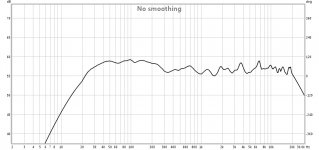
Here is a wide band measurement. This vertical scale is 5 db per division.
Now for the areas of interest:
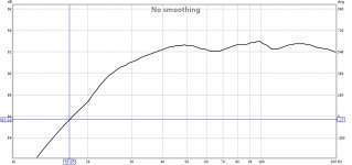
This is at 2 db per vertical division. And awesome measurement.
When I get back out of the big bad city I will do an overlay with the simmed box.
Great results Ron! (Bach On)
We can address the 16 hertz deficiency with a few tricks.
Principally there is a way to add passive equalization in line between the Roll's unit and your amplifier.
I'd have to look up the calculations, and maybe Zero D will beat me to it.
The parts are very cheap.
And now that you have a defined roll off it is not so difficult to correct.
Ron has coughed up an .mdat file.
And low and behold he has done sum great work.

Here is a wide band measurement. This vertical scale is 5 db per division.
Now for the areas of interest:

This is at 2 db per vertical division. And awesome measurement.
When I get back out of the big bad city I will do an overlay with the simmed box.
Great results Ron! (Bach On)
We can address the 16 hertz deficiency with a few tricks.
Principally there is a way to add passive equalization in line between the Roll's unit and your amplifier.
I'd have to look up the calculations, and maybe Zero D will beat me to it.
The parts are very cheap.
And now that you have a defined roll off it is not so difficult to correct.
And you would be surprised as to how easy it is to get a reflection in your measurement that can be lining up very well with a harmonic.
I'm still trying to wrap my head around the idea that a reflection will show up as a higher frequency in an RTA measurement.
To me, it looks like what I'd expect if something's being badly overdriven. If that distortion is not audible, then it's likely that the input channel on the PC running TrueRTA is being overdriven.
Switching it to oscilloscope mode and looking at the shape of the waveform before conducting the measurement should quickly indicate if this is the case. If the input is being overdriven, the top and bottom of the waveform will be flattened.
To me, it looks like what I'd expect if something's being badly overdriven. If that distortion is not audible, then it's likely that the input channel on the PC running TrueRTA is being overdriven.
Another thing - if the input is actually being overdriven, the end result may be a measured result that shows an FR that's a lot flatter than it really is. I suspect that may be issue behind some TH FR tests that were published here some time ago that seem to show the out of band peaks disappearing at higher SPL levels. As these peaks can be significantly higher than the passband, my guess is that their disappearing at higher SPL levels might have been caused by the measuring equipment being overloaded at those frequencies.
Ron has coughed up an .mdat file.
And low and behold he has done sum great work.
View attachment 493371
Here is a wide band measurement. This vertical scale is 5 db per division.
Now for the areas of interest:
View attachment 493372
This is at 2 db per vertical division. And awesome measurement.
When I get back out of the big bad city I will do an overlay with the simmed box.
Great results Ron! (Bach On)
We can address the 16 hertz deficiency with a few tricks.
Principally there is a way to add passive equalization in line between the Roll's unit and your amplifier.
I'd have to look up the calculations, and maybe Zero D will beat me to it.
The parts are very cheap.
And now that you have a defined roll off it is not so difficult to correct.
Mark,
I'm too old to do back flips. But thanks for the positive results and overblown praise. I used the driver recommended by several here and followed Oliver's design. If it came out good it was due to that.
I got the capacitors and have disassembled the Rolls unit. The eight original caps look fairly easy to remove from the circuit board. But I've got to go buy some desoldering supplies. And we're going to be removing the speakers and putting up the sheetrock and insulation tomorrow. I have to do the work when I can get the helpers. So it may be a few days before I do the Rolls.
I'm going to do the re-enforcement on the buzzy and leaky triangular box.
Then I plan to put the two homemade bass boxes side by side and run some measurements on them playing together.
Those big Bourdon pipes should leave July 27th. All the speakers will then go to their correct places. Then I can begin testing and measuring the sound pressure levels out in the Sanctuary.
Keep your fingers crossed!
Bach On
Mark's handling of the traces sure look wonderful to me. Exceptional bass. No doubt almost everybody who posted here is curious to see the sim prediction compared on the same axes to the mic results.
I'd hardly fret over the little droop at 16 Hz. It could be caused by any number of things in the chain of input or the chain of measurement. And it can be converted to any "house curve" needed any time at all.
Never the less, I think it would be helpful to see what input is driving the speaker instead of continuing speculation about the Rolls gizmo.
But what are we looking at? Are we up-close-and-personal or in-the-pews? Labelled "unsmoothed" but doesn't look like it?
Is that speaker nearly flat to 20kHz???? Where can I buy one?
Design, build, test.... iterate.
BTW, are you visiting any "big bad city" I might be living in having PanAmerican games going on?
Ben
Last edited:
@ Bach On
Before you remove the capacitors, make SURE you note the Polarity of EACH one. Maybe use a marker pen on the PCB to indentify the Negative leads. Don't over heat the PCB tracks. A few seconds should be enough to free each lead, & then resolder in the new ones. Don't blow on the joints, as it will create a bad ones.
@ mwmkravchenko
Adding passive equalization in line between the Roll's unit & the amplifier, could work. As you suggested it, i'll let you post the details. Alternatively, the Rolls could be modified to incorporate a similar effect.
@ Bach On
Before you remove the capacitors, make SURE you note the Polarity of EACH one. Maybe use a marker pen on the PCB to indentify the Negative leads. Don't over heat the PCB tracks. A few seconds should be enough to free each lead, & then resolder in the new ones. Don't blow on the joints, as it will create a bad ones.
This tactic seems unrealistic in advance of MEASURING the problem, if any. And in light of how trivial it would be to correct it later without recourse to a soldering iron.
But if you proceed, be sure to test the speaker output before and after, but without moving the speaker, mic, or gear in-between.
To test the electric signal that feeds the amp (assuming the amp is OK), all you need is an ordinary audio cable. What's the hitch?
Ben
Last edited:
BTW, are you visiting any "big bad city" I might be living in having PanAmerican games going on?
Just Ottawa. Sometimes I still work as a carpenter to get away from projects over here that drive me to derision. And to make some money that fills in the lulls between peaks.
The past year was a very difficult one in which I did a great deal of work for clients that decided not to pay me. Still catching up on that front.
The joys of being self employed.
@ mwmkravchenko
Adding passive equalization in line between the Roll's unit & the amplifier, could work. As you suggested it, i'll let you post the details. Alternatively, the Rolls could be modified to incorporate a similar effect.
What I would do is make a high pass filter. Cut all the stuff higher than the signal that we want to boost. Then we can use the gain of the Rolls unit to level everything off.
Some place I have stashed away a calculator for such little circuits.
But.
If the Rolls unit was in the signal path in the measurements I posted from Ron, then as ZD says we have to address this roll of problem first.
I can't stress enough to mark the polarity of the caps before you monkey with them. If you have a cell phone take a picture of the board.
I'm still trying to wrap my head around the idea that a reflection will show up as a higher frequency in an RTA measurement.
To me, it looks like what I'd expect if something's being badly overdriven. If that distortion is not audible, then it's likely that the input channel on the PC running TrueRTA is being overdriven.
Switching it to oscilloscope mode and looking at the shape of the waveform before conducting the measurement should quickly indicate if this is the case. If the input is being overdriven, the top and bottom of the waveform will be flattened.
I'm not exactly typing in all that I'm thinking. And that has caused the problem.
You are perfectly correct that a reflection cannot generate a sound of it's own.
No argument from me on that front.
But what I have seen is that the SPL level of the harmonic can be influenced by the distance of the reflection points if there are correlations between the harmonic wavelength and the distance away from a reflective surface.
Here is a simple example. Put a cabinet under test 8 feet away from a reflective surface. Play a 32 hertz tone and look at the height of the harmonic at 64 hertz. That would be the first harmonic right? 8 feet is also roughly the half wavelength of the first harmonic. When these things line up they can influence the measurement outcome.
And like you said they cannot generate any sound that is not there in the first place. But they can amplify it if the reflection distances line up with the harmonics in either full, half or quarter wavelength.
Take a wide band sweep and you always have to know the distance from the floor or ceiling. Why to gate out the reflections or they muddy up the measurement.
With the sweep Ron used it is not gated in the time domain if I remember correctly. I think REW using a rolling frequency selective gating to keep a clean measurement. Similar to a twin t notch filter used in distortion measurements.
But what I have seen is that the SPL level of the harmonic can be influenced by the distance of the reflection points if there are correlations between the harmonic wavelength and the distance away from a reflective surface.
With the sweep Ron used it is not gated in the time domain if I remember correctly. I think REW using a rolling frequency selective gating to keep a clean measurement. .
You're right about REW being careful about how wide open is the window. That includes the REW distortion, of course. Although ambient noise at the freq of the sweep does get recorded.
Ben
What I would do is make a high pass filter. Cut all the stuff higher than the signal that we want to boost. Then we can use the gain of the Rolls unit to level everything off.
Some place I have stashed away a calculator for such little circuits.
But.
If the Rolls unit was in the signal path in the measurements I posted from Ron, then as ZD says we have to address this roll of problem first.
I can't stress enough to mark the polarity of the caps before you monkey with them. If you have a cell phone take a picture of the board.
The Rolls unit has not been used for anything yet.
I can clearly see that the old and new caps have the minus lead marked. I thought I'd use a red magic marker to mark the position for positive lead on the circuit board.
BO
The Rolls unit has not been used for anything yet.
I can clearly see that the old and new caps have the minus lead marked. I thought I'd use a red magic marker to mark the position for positive lead on the circuit board.
BO
OK so the roll off on the Rolls unit will not help us that's for sure.
Marker to the rescue.
Good idea to mark the circuit board!
I see a potential issue with inserting a device designed to shape the frequencies for the triangular box.
Recap of the current plan:
Two outputs from the Artisan Sound Engine will contain the pedal signals. I do not think any of these samples are stereo. So output channels 7 and 8 will be identical.
Channel 7 will be plugged into one of the XLS1000s. The crossover will be set at 96 and the amp will be set for HIGHPASS. A limitation of these amps is that this means only one signal path is supported. So Input Channel 1 of the XLS1000 will be used. Signals to input channel 2 will be ignored. BUT both output channels will send signals. My current plan is to use output channel 1 to power an Allen HR100. It has a 10 inch woofer and a horn and has a frequency response range from 40 to 18,000 Hertz. I might be able to utilize another HC12 run from channel 2 of the XLS1000. But I'm anticipating that I won't have space for it in the speaker chamber.
Channel 8 from the sound engine will be plugged into input channel 1 of the XLS1500. Crossover at 96 Hz. Amp set in LOWPASS mode. So both outputs will carry the signal from input channel 1. Input channel 2 is offline.
Output channel 1 of the XLS1500 will be routed to the triangular box. Output channel 2 of the XLS1500 will be sent to the box with the two Dayton 15 inch speakers.
This configuration allows the gain knobs on output channels 1 and 2 to work independently. So the balance between these two boxes can be adjusted.
Here's the nature of my question. If some specific circuit is designed to shape the signal for the triangular box, it is going to also go to the twin dayton speaker box.
My uninitiated read is that it might be better to wait until I do some measurements with both bass cabinets playing together.
Does that long explanation make sense?
BTW, the vendor where I bought the Crown amps called. The XLS1502 now can send input channel 1 through a lowpass filter and input channel 2 through a highpass filter. The XLS models we have have only one DSP circuit for filtering. So you get only Lowpass OR Highpass at the same time.
Bach On
Last edited:
A picture is needed, at least for the slower ones like me. I suspect things can be managed more simply than you think.Does that long explanation make sense?
Draw it, annotate, fax to your computer (if you don't have a scanner or a Kinko office), post it.
About that trace Mark posted with the flat 20-25kHz response. Either it is the world's greatest woofer ever made or could it be the mic calibration curve? What are we looking at?
Ben
Last edited:
I'm running into a bit of a quandry with the file from Ron.
I think you are spot on Ben. This is the mic calibration. Not the woofer response
On my laptop I can open up the file and get what I posted. It's under the normal SPL tab.
On my big rig I usually work on I get something completely different. The two are not the same at all.
The difference is on the laptop I'm running REW 5.0 and on the large computer I'm running REW5.1
I have not set the mike compensation check box in REW on the lap top. But it eerily does look like it when you open up the file in a wideband window.
I never had it set up like that on the lap top.
Only a truncated low end result that pretty much coincided with the potential for the existing enclosure.
So sorry to pop your balloon Ron, but I think something is a bit iffy with that measurement. I should have looked at it in a wide band setting first. Because a woofer is not flat out to Bat music.
In REW 5.2 I get something that looks like this:
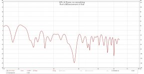
So is this a bad measurement?
Nope.
It is an actual measurement of the driver and enclosure in a room. And it looks pretty realistic.
As one gentleman pointed out a bit earlier a nearfield measurement would have been much cleaner. And without asking Ron I thought that is what he had done. Sent me a nearfield measurement.
You have your nulls, which we would expect in a room, and you have the rolling hills that you get in a listening position measurement. So this is still a great measurement. Pat on the back is still there Ron!
You have a response that is plus or minus 2.5 db over the bulk of the systems response. The null at 38 hertz is most likely a null from enclosure placement. And that is easy to test by rotating the enclosure 90 degrees and taking another measurement. If the null changes at all you have discovered that it is a null!
I should point out that this is a raw measurement with no smoothing what so ever. Look at it through 1/6th octave smoothing:
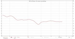
Looks a little different with this level of ripple reduction.
Here is the standard marketing 1/3rd octave smoothing. It is nuts! Details? What details?
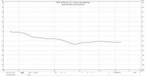
What else is great to see is that your amplifier is not unduly rolling off your low end to much. So with the fix on the Rolls interface you are working on you are golden.
What should have set off the bells is the stated bandwidth of the measurement! In Ron's file he states the measurement bandwidth on the file name. Unfortunately I used the wrong machine to view the file.
Wish I had seen this in the lap top. Would have looked much less silly at this point. There will be an update done to REW on that little machine!
@ Master ZD
You have made be brush up on the correct formula for calculating the passive EQ should we need it. Thanks!
Old dog can learn new tricks.
I had a nice spreadsheet hiding in among the files.
I think you are spot on Ben. This is the mic calibration. Not the woofer response
On my laptop I can open up the file and get what I posted. It's under the normal SPL tab.
On my big rig I usually work on I get something completely different. The two are not the same at all.
The difference is on the laptop I'm running REW 5.0 and on the large computer I'm running REW5.1
I have not set the mike compensation check box in REW on the lap top. But it eerily does look like it when you open up the file in a wideband window.
I never had it set up like that on the lap top.
Only a truncated low end result that pretty much coincided with the potential for the existing enclosure.
So sorry to pop your balloon Ron, but I think something is a bit iffy with that measurement. I should have looked at it in a wide band setting first. Because a woofer is not flat out to Bat music.
In REW 5.2 I get something that looks like this:

So is this a bad measurement?
Nope.
It is an actual measurement of the driver and enclosure in a room. And it looks pretty realistic.
As one gentleman pointed out a bit earlier a nearfield measurement would have been much cleaner. And without asking Ron I thought that is what he had done. Sent me a nearfield measurement.
You have your nulls, which we would expect in a room, and you have the rolling hills that you get in a listening position measurement. So this is still a great measurement. Pat on the back is still there Ron!
You have a response that is plus or minus 2.5 db over the bulk of the systems response. The null at 38 hertz is most likely a null from enclosure placement. And that is easy to test by rotating the enclosure 90 degrees and taking another measurement. If the null changes at all you have discovered that it is a null!
I should point out that this is a raw measurement with no smoothing what so ever. Look at it through 1/6th octave smoothing:

Looks a little different with this level of ripple reduction.
Here is the standard marketing 1/3rd octave smoothing. It is nuts! Details? What details?

What else is great to see is that your amplifier is not unduly rolling off your low end to much. So with the fix on the Rolls interface you are working on you are golden.
What should have set off the bells is the stated bandwidth of the measurement! In Ron's file he states the measurement bandwidth on the file name. Unfortunately I used the wrong machine to view the file.
Wish I had seen this in the lap top. Would have looked much less silly at this point. There will be an update done to REW on that little machine!
@ Master ZD
You have made be brush up on the correct formula for calculating the passive EQ should we need it. Thanks!
Old dog can learn new tricks.
I had a nice spreadsheet hiding in among the files.
- Status
- This old topic is closed. If you want to reopen this topic, contact a moderator using the "Report Post" button.
- Home
- Loudspeakers
- Subwoofers
- 16Hz for church organ