Hello. Chad.
I am very grateful and it will be exciting to see your other drawing.
I have a couple Sonido 144, which sounds great will try try them. otherwise I have a couple of 166 that I can put on it does not work, but Sonido 144 sounds excellent.
Austin 166, I have now heard so much gone on so I just have to build a couple of the "curved".
Forsman
I also have this drawing from planet10 site, but the "curved" look quite fantastic.
So while I put my hope in hifiZen work
cheers
Sweden
Making progress...
The basic dimensions are all in, I used exactly 0.7" for the ply thickness. Everything is lining up very nicely now, I had to shave a few hundredths of an inch here or there, but such fine trimming should be of zero consequence. There is only one significant difference - I ended up with a slightly shorter 2nd divider vs. the original, so the total horn length might be a few tenths of an inch shorter. Again, I would say this is probably of no consequence, given the wavelengths. Most important, the cross-sectional areas through the horn should all be spot-on now.
OK, it's late now... bedtime. So tomorrow evening I'll work on the actual drawing layers, driver hole placement, baffle, etc, and hopefully start adding some dimensions.
Attachments
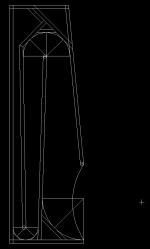
And just a note: when I add the dimensions, I'll also specify each bend center point + radius, so that you can build either a curved version, or the sectioned flat-pieces version from the same plan. I'll do a separate detail drawing for the teardrop flare at the horn mouth.
Fantastic!
hifiZen:
Sorry for asking, I’m new here on the diy-forum and doesn’t know who is knowing who so maybe it’s a stupid question, but. Is it possible to incorporate the information from those drawings (Dave/planet10) into your work as well? More workload of course, can I be of any help?
/Forsman
hifiZen:
Sorry for asking, I’m new here on the diy-forum and doesn’t know who is knowing who so maybe it’s a stupid question, but. Is it possible to incorporate the information from those drawings (Dave/planet10) into your work as well? More workload of course, can I be of any help?
/Forsman
paba said:Or another stupid question, can that file (curved layertone) be taken to CNC equipped shop locally and have them cut out all the pieces?
My mom used to tell me "honey, there are no stupid questions", then I got married.
Now, even after 35 yrs, I love my wife so much it hurts, but have certainly learned that most of my questions aren't "not stupid"
Or does each CNC machine require unique programming?
Thanks
paba
that pretty much depends on the CNC machine - my shop uses a Morbidelli Author 503 can be programmed at the console for relatively simple routines, but something like this would normally originate in AutoCad, and be translated through a compiler (such as Pattern Systems DrillMate) before being networked to the machine.
paba said:If yes, then is that file for sale?
The file i have is the one that Tony (layertone) used as the basis for CNCing his (it is a dwg).
I have forwarded the file to Forsman. As Chris said, what you need depends on the CNC you have.
Donations to keep the FH site active & growing are always welcome. The base drawings will be free, whether any required donation is required for actual CNC files will depend on what the person who creates them feels is appropriate. We do hope they will be available one way or another.
The file from Tony does have a ghost of the original straight panel drawing in it, either Chad or i will compare/utilize that to detail Chad's plans.
dave
planet10 said:Speaking of curved version... i now have what exists of the dwg files from Tony (layertone's) collaboration with Ron for the original curved version.
dave
Fantastic! I got your email... I'll roll this data in as best I can. May not have much time in the next two or three days, but come the weekend...
")
Much appreciated.
planet10 said:I have forwarded the file to Forsman.
Thanks a lot Dave! Will work with it and get back.
/Forsman
Re: Re: yes please do, it's about time i use my 166es-r 8•)
wrt the A166,
closest i can come to making heads or tails of that would be from jhon atkinsons accelarometer measurments of ed schillings horn shoppe horn's^ - it's cabinets vibrational behavior found a 'fairly strong mode at 254Hz on all surfaces", others at 610Hz which were "very strong on the sidewall", and another just above 100Hz around the drivers lf tunning fq. what i think may be applicable here is in J.A.'s pointing out that "the horn's high sensitivity" which he measured 94db B weighted/2.83V/m., (i don't where all that gain came from of a 90db 108ez), will render those resonances inaudible. "for a given SPL, the driver signal to the speaker will be considerably lower than with a conventional speaker, reducing the influence of the cabinet behavior".
perhaps there's another reason for the echo?
^vol.27 no.1 $$phile 1/04 p.102
serenechaos said:
i don't know about not doubling the side walls being a good idea, unless light weight is more important than sound quality...
i didn't double the side walls on the 166esr austins i built, was going to double them later if i liked the cabs, & thought they needed it.
if i planned on keeping/using them long term i definitely would.
you can feel the sidewalls vibrating, and hear a "echoey" sound from the back wave.
-- may be partly from the side wall vibration?
(not just the long, dissimilar back wave path length to the front wave).
wrt the A166,
closest i can come to making heads or tails of that would be from jhon atkinsons accelarometer measurments of ed schillings horn shoppe horn's^ - it's cabinets vibrational behavior found a 'fairly strong mode at 254Hz on all surfaces", others at 610Hz which were "very strong on the sidewall", and another just above 100Hz around the drivers lf tunning fq. what i think may be applicable here is in J.A.'s pointing out that "the horn's high sensitivity" which he measured 94db B weighted/2.83V/m., (i don't where all that gain came from of a 90db 108ez), will render those resonances inaudible. "for a given SPL, the driver signal to the speaker will be considerably lower than with a conventional speaker, reducing the influence of the cabinet behavior".
perhaps there's another reason for the echo?
^vol.27 no.1 $$phile 1/04 p.102
Okay, I did the import of layertone's drawings into mine. So now I have three versions overlaid (well, 4 actually, but I'm discarding my earlier drawing)... the panelized drawing in the pdf, Tony's curved version, and my reconstruction from Ron's rev G. dimensions.
All three match very closely except, as expected, around the second bend... with the corrections noted by bobmar and the dimensions from Ron's original plan, the partition extends up farther than it does in the existing plans, such that the width around the second bend is a continuous expansion, rather than getting wider at the top, and then narrowing again at the exit side of the bend.
I also note that Tony used a slightly thicker panel for his curved version, so in his drawing, things are shifted around slightly.
~~~~~~~~~~~~~~~~~~~~~~~~~~~~~
So, for those who are interested, here is the methodology I used to reconstruct the horn profile from Ron's rev G drawing / dimensions:
As in Ron's plans, I put the x,y origin at the lower left corner. I used 48.00" inches total height, and 15.00" (Ron's drawing shows 15.01") total depth. And I made all panels exactly 0.70" thick.
I then worked outward along the horn path, starting from the horn throat entry point. This is specified in Ron's drawing as x,y coordinates (2.00,39.93). This point matches precisely in all of the plans I have seen.
Next, for each bend, I calculated a radius based on the specified width at the start & end of the bend. For the first bend, start=1.92", middle=2.13", end=2.45". Adding 0.7" (panel thickness) yields the diameter of the curve... so first bend radius = 2.535". I then position a r=0.35" circle at the appropriate point to give the correct start/middle/end widths, and that circle becomes the rounded end of the panel.
For the second bend, widths are: start=4.05", middle=4.46", end=4.72", so the curve radius is 4.735" for a 0.700" panel thickness. Since I wanted to keep all the panel thicknesses as 0.7" for simpler construction, rather than making that first 45 degree piece 0.5" thick. So again working from the horn throat entry point, I drew a 45 degree angle, and offset that by 0.7". I then positioned the correct radius circle tangential to that and the first divider panel. The position of the second divider's end point followed, as did the position of the remaining panels to form the rest of the bend. This is where the discrepancy arose - my second panel is slightly taller (by 0.06") than shown in Ron's plan, but as a trade-off, all the panels can be made exactly 0.7" thick, and the corner dimensions remain correct per the original drawing.
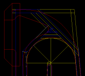
For the horn mouth, I positioned a r=0.35" circle for the panel endpoint - 15" up from the bottom of the horn mouth (y=15.7") - and connected a tangent from that circle back to meet the second bend curve at a tangent. Since there were no dimensions for it, the horn mouth curve was found by drawing a 45 degree angle up from the bottom corner of the horn mouth at (15.00,0.70) to it's intersection with the second divider panel., and fitting a radius to round off that corner. It's not quite tangential where it meets the vertical panel (pretty close), but it does meet the bottom of the horn mouth at exactly zero degrees.
Anyway, here's a screenshot overlay of the three versions of second bend. Blue is the old panelized version (available now as pdf on planet10's site), red is Tony's layered / curved version, and yellow is the new profile I built up from Ron's original rev. G drawing.
There is more work to do on my end before the plans are ready. Stay tuned...
All three match very closely except, as expected, around the second bend... with the corrections noted by bobmar and the dimensions from Ron's original plan, the partition extends up farther than it does in the existing plans, such that the width around the second bend is a continuous expansion, rather than getting wider at the top, and then narrowing again at the exit side of the bend.
I also note that Tony used a slightly thicker panel for his curved version, so in his drawing, things are shifted around slightly.
~~~~~~~~~~~~~~~~~~~~~~~~~~~~~
So, for those who are interested, here is the methodology I used to reconstruct the horn profile from Ron's rev G drawing / dimensions:
As in Ron's plans, I put the x,y origin at the lower left corner. I used 48.00" inches total height, and 15.00" (Ron's drawing shows 15.01") total depth. And I made all panels exactly 0.70" thick.
I then worked outward along the horn path, starting from the horn throat entry point. This is specified in Ron's drawing as x,y coordinates (2.00,39.93). This point matches precisely in all of the plans I have seen.
Next, for each bend, I calculated a radius based on the specified width at the start & end of the bend. For the first bend, start=1.92", middle=2.13", end=2.45". Adding 0.7" (panel thickness) yields the diameter of the curve... so first bend radius = 2.535". I then position a r=0.35" circle at the appropriate point to give the correct start/middle/end widths, and that circle becomes the rounded end of the panel.
For the second bend, widths are: start=4.05", middle=4.46", end=4.72", so the curve radius is 4.735" for a 0.700" panel thickness. Since I wanted to keep all the panel thicknesses as 0.7" for simpler construction, rather than making that first 45 degree piece 0.5" thick. So again working from the horn throat entry point, I drew a 45 degree angle, and offset that by 0.7". I then positioned the correct radius circle tangential to that and the first divider panel. The position of the second divider's end point followed, as did the position of the remaining panels to form the rest of the bend. This is where the discrepancy arose - my second panel is slightly taller (by 0.06") than shown in Ron's plan, but as a trade-off, all the panels can be made exactly 0.7" thick, and the corner dimensions remain correct per the original drawing.
For the horn mouth, I positioned a r=0.35" circle for the panel endpoint - 15" up from the bottom of the horn mouth (y=15.7") - and connected a tangent from that circle back to meet the second bend curve at a tangent. Since there were no dimensions for it, the horn mouth curve was found by drawing a 45 degree angle up from the bottom corner of the horn mouth at (15.00,0.70) to it's intersection with the second divider panel., and fitting a radius to round off that corner. It's not quite tangential where it meets the vertical panel (pretty close), but it does meet the bottom of the horn mouth at exactly zero degrees.
Anyway, here's a screenshot overlay of the three versions of second bend. Blue is the old panelized version (available now as pdf on planet10's site), red is Tony's layered / curved version, and yellow is the new profile I built up from Ron's original rev. G drawing.
There is more work to do on my end before the plans are ready. Stay tuned...
Attachments
Just to summarize:
Overall, the dimensions I reconstructed worked out very well, and agree within 0.06" of Ron's original drawing (most dimensions in my new drawing are actually within 0.01" - better than anyone could hope to actually cut from real wood!). So I think I'm happy with the reconstructed horn profile.
One thing I just noticed needs to be addressed is the volume of the compression chamber. for some reason, after I put the tangential lines in place to build the second bend, and extended those out at 45 degrees, the position of the compression chamber rear wall no longer agrees with the older plans (or Ron's dimensions!). So I'll have to look closer at that, but I'm confident the horn profile is good, and that's the main thing to get right.
OK, I've made some progress... cleaned out a whole bunch of my older work from various layers, and generally tidied up the whole drawing. About 70% of the dimensions are in, and I was going to plot a preliminary file to post here, but now I'm hung up on the silliest thing -- I can't figure out how to plot to pdf (although I did it last time, somehow).
Even though I managed to do it last time, the results weren't so satisfactory. So I'm looking for a good option to plot from AutoCAD / Win XP to pdf, either through vmware's "virtual printer", or some other way (Cute PDF, PDFCreator, ... ?).
Anyone who can suggest a good option? Freeware preferred - I'm primarily on Mac, and only ever go into windows/vmware for AutoCAD, LTSPICE, or SoundEasy.
- Status
- This old topic is closed. If you want to reopen this topic, contact a moderator using the "Report Post" button.
- Home
- Loudspeakers
- Full Range
- 166es-r in a austin a166 & construction ?