Actually the curved version is first as used in a sim(1). All i did was to adapt flat panels to the curve as close as possible. Tony has the actual curved programming as he developed it from my calculated radi points.
So , the original order was:
(1). a straight expansion (no curves)
1. A curved design extrapolated from the straight.
2. A flat panel design developed from the curved version.
3. Re-design from the flat panel design to another curved version by Tony.
All this was lost during a Windows crash. This taught me to back up my work.
I will be gone for one week to have a wire coil installed in my left ventrical(sp?.) This is suppose to increase blood flow and possibly
prevent me from having to have by pass operations in the future.
Later
ron
Thanks Ron.
That does not sound like fun. On the other hand, preventive maintenance is very much preferable to "emergency repairs". Best wishes, I hope the operation and recovery go smoothly. And may your nurses be... bountiful.

REC1 said:I will be gone for one week to have a wire coil installed in my left ventrical(sp?.) This is suppose to increase blood flow and possibly
prevent me from having to have by pass operations in the future.
That does not sound like fun. On the other hand, preventive maintenance is very much preferable to "emergency repairs". Best wishes, I hope the operation and recovery go smoothly.
And may your nurses be... bountiful. I'm seriously considering building these.
One question about the PDF plans for this A166; it is mentioned in the notes that the second 180 bend (larger of the two) measurements of the three widths of the flair around the curve are wrong in the plans. Would that not change the angles of the center divider piece and the back piece slightly? How to then maintain all proper dimensions? Just push everything in from the back on the side view enough to accommodate the slightly smaller dimensions?
The correct dimensions on that bend stated in the notes on page one say 4.05" 4.46" and 4.72" according to Ron. The drawing shows 4.13" 5.54" and 4.80". I'll attempt to answer my own question a bit in that; 4.13" is so close to the 4.05" and the 4.80" close to 4.72" that would it be enough just to lower the "ceiling" piece at the top of the curve to the desired 4.46".
I'd hate to have to fuss with the slight angles on the center divider if it were not critical that far along the horns length.
TIA for the help!
Chris
The drawing shows 4.13" 5.54" and 4.80".
One of the reasons is the sim figures did not match the dwg dimensions. I also use a round over ,piece of rounded trim, on the top of the panel across the width, this was not included in the dwg.
The original dwg was made with an early Turbo Cad software, at that time there was no point lock and i never use a grid. So the stated dimensions are exact the dwg dimensions are what Cad gave me.
Just stay as close to the stated dimensions as possible and it will work out.
ron

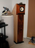
A166 with FE166 & T90
I finally finished these up, I have to admit the construction was a little more difficult than I anticipated. On top of it I had a friend help me cut the panels on his table saw and I either miss communicated or he misunderstood and I ended up with the with the sides being 1" wider than plan. I did not realize it until I had glued them up less one side. In order to bring the interior back I had to cut pieces to fit inside the baffles. In any case I ended up with a well dampened box (and quite heavy). To make the rounded curves I purchased some adhesive backed linoleum and filled the voids with sand. They do sound quite amazing throwing out quite a good sound stage with a remarkable amount of bass. They are now on the Pass F4 but I also have a pair of 300b set amps. I prefer the set amps they are less dampened and they are a better all around match but the hum was driving me nuts. I will be converting them to DC filaments and my tube pre is giving me fits with oscillation ( the joy of DIY).
Bill
Attachments
Thanks Ron,
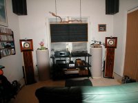
Chris that was my plan, but truthfully the set amps have plenty of power by themselves (will try it anyway). The room is quite small (and square) hence the the bass traps to breakup standing waves. Oddly it was Nelson Pass that recommended the FE166 as a sanely priced full range driver. His current pet preamp is the B1, but he plans on a B4 with Eq network for full range drivers. I am not sure if it will based on base reflex cabinets and how it will interact with the BLH , it will reasonable inexpensive so what the heck. At the pace I have been trouble shooting my tube preamp I could build it and be enjoying the music in the mean time.
Bill
Attachments
Oddly it was Nelson Pass that recommended the FE166 as a sanely priced full range driver.
Nothing odd about it. I saw the 166 as a balance between the 126 and the 206 at a very good price/performance ratio. TC (RIP) saw , i believe, the same thing for the Abbys but i probably would have gone with the 167 instead for a TQWT.
Hows that HF horn working out?
By the way have the surgeon add a cap to that coil and see if he can equalize your hearing
Getting old and liking music is a difficult thing. If i am at home in SC i get complaints from the masses that the music is too loud. I really need a bright mid and high to hear properly. SO says get a hearing aid but vanity ( even at my age) sets in so i would rather bug someone else and nudge the person next to me and ask "what did he say"?
ron
REC1 said:
Hows that HF horn working out?
What is it?
Where is it crossed in?
I'm using a JBL 2405 with an oil cap, comes in ~ 10kHz.
Are you using anything on the bottom?
Using a down-firing sub built into the rear deflector works great.
The horn is a Fostek T90 crossed with a single Fostek copper cap (not sure of value and sealed inside). The jury is out on it and I should probably disconect and get used to with out it and reconect it. I have been moving amps around so critical asessment has been thrown out the window. I had the sets on the workbench and resoldered a bunch of joints and fideled with the star ground and improved the hum from 15 mv to under 5mv. Then my XBOZ preamp decided it didn't like driving them, since they have built in volume controlers I may drive them from the source directly (need longer cables).I have a sub system with a Reckhorn AMP / Equilizer but want to get the rest stabalized befor integrating it. I am always at odds with my ear calibration, I never realy trust them. I am looking into Siegfried Linkwitz's toneburst sytem of measurement. I would like next to build a set of his Pluto speakers triamped with some alephs I have laying around and a Jan Diddon style modified Beringer DCX2496 speaker management system.
Bill
Bill
Greetings from Shenzhen... Took a bit of a hiatus to focus on building my F120A speakers in prep for BAF'08, and then work got pretty busy again. Now it turns out, I'm on one of those business trips where there isn't a lot to do, so I'm plugging away on the A166 plans again.
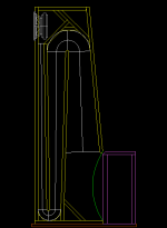
Referring back to Ron's comments about the history of the pdf plans, I took some measurements of what I've got in CAD right now... mostly looking at the horn expansion to see if I got the corners right. Have a look at the attached photo. For the corners, I used the centerline arc length to calculate the expansion rate (maybe centerline is not the right length to use for this, but it's a start), and came up with the following. This is the expansion rate measured from the curves, in terms of width increase per unit length:
1st section: 0.017
1st bend: 0.117
2nd section: 0.047
2nd bend (the big one): 0.082
3rd section: 0.124
I didn't bother to calculate expansion at the horn mouth due to the difficulty of measuring it on the plans.
So two questions arise:
1) the 1st bend at the bottom seems to expand quite a bit more than the preceding and following straight sections. Maybe it doesn't matter due to the short length of the bend, but does it seem correct? The dimensions for this bend are quite accurate, as shown in the pdf plans.
2) The first angle in the large bend does not really follow the circular curve very well, cutting into the arc quite a bit. This creates extra room for the compression chamber, badly needed with the 166ES-R's huge magnet, but will it affect the horn performance?
I've been thinking about the magnet size problem, too - it's really a giant pancake that's going to be quite restrictive in terms of airflow between the cone and compression chamber, so I'm a bit concerned about that. Anyway, I'd like to focus on getting the horn taper right first, and maybe I can adjust the suprabaffle and / or CC dimensions to better accommodate the big magnet after.
Attachments
Here's a pdf of my reconstruction as it is now, with dimensions shown on the first two pages. For the most part, I've tried to keep it as consistent as possible with the dimensions on pages 3 and 4 of the available pdf plan, with a few dimensions lifted from page 6. But there are some inconsistencies - a number of dimensions didn't come out the same, or didn't reconcile once I drew it up. So I've had to prioritize what I would guess are the more important dimensions, and make a few small trade-offs here and there.
Please take a look, and if you see something which looks to be in error, please let me know so I can adjust the design.
I will probably work on the compression chamber area of the design some more, in order to better accommodate the giant 166ES-R magnet. I will keep the overall volume the same, but hopefully improve clearance for airflow around the magnet. I will add provision to increase or decrease the chamber volume easily by bolting in extra pieces of plywood at the back of the CC (it is already double-thickness). The top 'lid' will be removable for easy access to the driver, CC, and a small compartment for binding posts, supertweeter crossover, or rear-facing tweeter, etc.
I haven't decided quite how I'm going to integrate the suprabaffle yet - I would like it to be removable / separate piece for experimenting, but also for cosmetic reasons - I want the option to finish the SB with a different veneer from the main body of the speaker. Pages 4 and 5 of the pdf show two different SB options that I've drawn up so far, along with the 166ES-R driver, accurately drawn from measurements of the real thing.
Attachments
- Status
- This old topic is closed. If you want to reopen this topic, contact a moderator using the "Report Post" button.
- Home
- Loudspeakers
- Full Range
- 166es-r in a austin a166 & construction ?