hifiZen said:Even though I managed to do it last time, the results weren't so satisfactory. So I'm looking for a good option to plot from AutoCAD / Win XP to pdf, either through vmware's "virtual printer", or some other way (Cute PDF, PDFCreator, ... ?).
....I'm primarily on Mac, and only ever go into windows/vmware for AutoCAD, LTSPICE, or SoundEasy.
The autoCAD file can be opened in either VectorWorks or Illustrator on the Mac and then (since pdf is the native graphics format) output to a pdf.
(if you have too much trouble send it to me and i'll do it)
dave
hifiZen said:Even though I managed to do it last time, the results weren't so satisfactory. So I'm looking for a good option to plot from AutoCAD / Win XP to pdf, either through vmware's "virtual printer", or some other way (Cute PDF, PDFCreator, ... ?).
I’m not sure this works with older versions of AutoCAD but it does with the 2009 version.
1. Click Output tab > Plot panel > Plot.
2. In the Plot dialog box, under Printer/Plotter, in the Name box, select the DWG to PDF.pc3 configuration from the Name list.
3. Under Paper Size, select a paper size that has the longer dimension listed first (if you want it in landscape orientation). For example, ANSI A (11.00 x 8.50 Inches).
4. Click OK.
5. In the Browse for Plot File dialog box, select a location and enter a file name for the PDF file.
6. Click Save.
Maybe this isn’t the answer to the problem but it is an idea. Which version of AutoCAD do you have?
/Forsman
Bullzip did the trick. Alas, I do not have either illustrator or vectorworks, and ACAD 2000 doesn't appear to have the "DWG to PDF.pc3" config file.
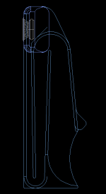
Anyway, here's the first page. Needs some work, but the main dimensions are there.
You may notice a discrepancy with the third dimension of the second bend... this is because I made the rear wall a tangent to the calculated arc, per my methodology description previously posted. Because of this, the rear wall is 0.03" beyond the arc at the dimensioned location. An artifact of the method I used to reconstruct the plans - there are arcs and odd angles involved, so some approximation was needed to get the drawing done. Not that 3 hundredths should matter, but I believe the other bend dimensions are exact.
The only remaining caveat is the compression chamber volume, which seems slightly different than what Ron drew originally. Sticking with 45degree angles only for the upper panels, I couldn't get the dimensions to match perfectly there, probably due to my choice to use 0.7" panel thicknesses only. Anyway, I haven't drawn in the supra-baffle piece yet (there are some outlines in the CAD file, but none shown here), and that will have an effect on the CC volume. For now, I leave it as an exercise for the builder to determine their baffle scheme and then factor in driver displacement etc, to arrive at the right CC volume by adding extra blocks in there, or removing some wood.
Speaking of which, anyone know the exact CC volumes for regular 166 and 166es-r? I ran across it somewhere, but it isn't in my notes... I'll search around some more and see if I can find it, but the A166 info is scattered across multiple threads on multiple forums, so it can sometimes be a bit tricky to locate specific bits of info!
I guess that's another thing I will do eventually - distill my notes and forum post clippings / quotes into a coherent format so that as all of the pertinent info is gathered in one place.
Attachments
2.74 liter C.C. volume for 166es-r
mp9 said:Ron Clarke ran the numbers for me and came up with, "CC volume=2.74 liters when a 12.7"x12.7"baffle is used for that driver. Either that or a 12.7 "round baffle."
Thanks mp9.
Hmm, I should add a few dimensions for the upper panels. Oh, and I should also point out that I drew the lines for either the 45 degree "shoulder" per the original plans, or for a more rectangular side profile, with the rear panel extending all the way up. Just in case you're wondering why that part doesn't look finished.
I don't see why you couldn't build either way, to suit your personal preference. The more rectangular profile creates a little chamber there, which could be used for, say, mounting the terminal cup, or a crossover cap for a supertweet, etc.
Here's a little better "preliminary" drawing.
More work to do, yet... I have the curved version to work up, plus dimensions for the horn profile itself, independent of the wood parts. Title block and other niceties, wedge, base plate, baffle and driver placement (plus CC volume corrections). It's turning out to be a little more than I thought, but what's here now covers all the essential dimensions.
More work to do, yet... I have the curved version to work up, plus dimensions for the horn profile itself, independent of the wood parts. Title block and other niceties, wedge, base plate, baffle and driver placement (plus CC volume corrections). It's turning out to be a little more than I thought, but what's here now covers all the essential dimensions.
Attachments
Originally posted by hifiZen Bullzip did the trick. Alas, I do not have either illustrator or vectorworks, and ACAD 2000 doesn't appear to have the "DWG to PDF.pc3" config file.
Sorry for being overexplicit with the pdf-printing tip, unnecessary of me. Very nice work! Looking forward to see the curved version also.
/Fredrik
hifiZen said:Here's a little better "preliminary" drawing.
More work to do, yet... I have the curved version to work up, plus dimensions for the horn profile itself, independent of the wood parts. Title block and other niceties, wedge, base plate, baffle and driver placement (plus CC volume corrections). It's turning out to be a little more than I thought, but what's here now covers all the essential dimensions.
I'm hoping i can just put your pdf up on the FH site when you are done... can the dimensions be a notch bigger and can AC do stacked imperial/metric dimensions?
dave
planet10 said:
I'm hoping i can just put your pdf up on the FH site when you are done... can the dimensions be a notch bigger and can AC do stacked imperial/metric dimensions?
dave
Absolutely.
OK, I've added the dual inch [mm] dimension text, and also tried making the dimensions larger. But, I wasn't able to make it even a small amount larger before parts of the drawing became too crowded and illegible, with leader lines going all over. I just did a test print, and although it does look pretty small on letter size paper, it doesn't seem unreasonably small to me. At least, there's always the zoom button on screen... I'm afraid it's about the best I can do without moving to a larger sheet size.
Anyway, I did a little cleanup just now, and added a third page showing the profile curve center points and radii. Getting closer...
Attachments
Nice drawings, the angles are a good idea, makes setting the saw up a doddle.
One method of making drawings easier to read when most people are only going to have access to a letter (A4) printer is to add the dimensions as a letter, than the last sheet has a table referencing the dimension lengths to the letters. Its extra work but dose allow letter size prints that are readable. If I remember vaughly you can assign variables in autocad which you can automaticly create a table from.
I do like these speakers and as I still have a pair of 166's minus a cabinet so I am realy (and have been for a while) tempted to build them. My main problem is convining the missis that we nead another sytem in another room! But as I have the use of a roll feed plotter I am going to print out some one to one plans and see how big they look in the flesh (sort of).
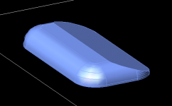
Another update...
Just wanted to show you guys what I've been playing with the past few days...
So I'm now working on a curved version of my own, optimized for the FE166ES-R. The main problem I've been faced with is the huge magnet blocking airflow into the CC. So I knew that a protruding baffle probably wouldn't work, since a straight-through hole would be completely choked off by the magnet, and a cone-shaped hole would end up too large to fit in the box dimensions. The driver pretty much needs to mount flush to a single-thickness front panel.
Two other objectives:
1) I want it to look good.
2) I'd like access into the CC for convenient stuffing adjustments etc.
So the other night I dreamt up how to accomplish the above and integrate a nice baffle into the design, which doesn't protrude forward. In keeping with the semi-layertoned construction, it makes judicious use of curves.")
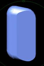
With a driver mounted flush to the front panel, the baffle needs to extend outward to the sides, and also upward past the usual top of the box. I decided to extend the top of the box up to the height where a 12.7" x 12.7" baffle would stop, and then add 'cheeks' on either side, to extend out to the correct width. The vertical extension uses a 2" radius round off, created with the layered CNC panels. The cheeks would be built up from laminated stacks of plywood, then shaped on a router & table saw. The largest roundover bit I could find is 1.5" radius, so that's the curve I used for the cheeks. A deep angled cut then tapers the back side of the cheeks in, forming a nice teardrop profile from above.
As a bonus, the cheeks can be made detachable, with access ports behind. These cutouts additionally provide some extra internal clearance around the sides of the ES-R's giant magnet.
I just finished modeling the cheeks in 3D... still need to finish working out the CC internals.
Just wanted to show you guys what I've been playing with the past few days...
So I'm now working on a curved version of my own, optimized for the FE166ES-R. The main problem I've been faced with is the huge magnet blocking airflow into the CC. So I knew that a protruding baffle probably wouldn't work, since a straight-through hole would be completely choked off by the magnet, and a cone-shaped hole would end up too large to fit in the box dimensions. The driver pretty much needs to mount flush to a single-thickness front panel.
Two other objectives:
1) I want it to look good.
2) I'd like access into the CC for convenient stuffing adjustments etc.
So the other night I dreamt up how to accomplish the above and integrate a nice baffle into the design, which doesn't protrude forward. In keeping with the semi-layertoned construction, it makes judicious use of curves.
With a driver mounted flush to the front panel, the baffle needs to extend outward to the sides, and also upward past the usual top of the box. I decided to extend the top of the box up to the height where a 12.7" x 12.7" baffle would stop, and then add 'cheeks' on either side, to extend out to the correct width. The vertical extension uses a 2" radius round off, created with the layered CNC panels. The cheeks would be built up from laminated stacks of plywood, then shaped on a router & table saw. The largest roundover bit I could find is 1.5" radius, so that's the curve I used for the cheeks. A deep angled cut then tapers the back side of the cheeks in, forming a nice teardrop profile from above.
As a bonus, the cheeks can be made detachable, with access ports behind. These cutouts additionally provide some extra internal clearance around the sides of the ES-R's giant magnet.
I just finished modeling the cheeks in 3D... still need to finish working out the CC internals.
Attachments
Re: Another update...
Just tuning in.
I’m really curious of the progress of the curved version and the possibilities of lending or buying drawings for my own project. I’ve scanned my home town for workshops that can do the CNC-milling and there are a couple companies that seem to be able to do it for a reasonable cost.
I would like to try to build this speaker with transparent sides using really thick Plexiglas (if I can find it to an acceptable cost). The interior lends its shapes from instruments like the saxophone and I really like to lay emphasis on that. Ecstatically my personal opinion is that it might look even better if it was possible to make the radius of the first and second bend a little bit bigger.
Does anyone know how the performance would be affected by increasing the radius of the first and second bend? As far as I’ve understood this design it is very well tuned and it wouldn’t be to smart to alter the length between the bends if their length are of importance for the performance. But this I don’t know, just sharing my thoughts.
I was playing a little bit in Autocad but I got outsmarted when it came to do curved cone surfaces. However it is just a little play with ideas. Would it bee possible to translate the cross section from a rectangle into a circle? I think I’ve read somewhere that the speaker first was designed with a circular cross section an then altered into a rectangle so that would be possible to build. One could CNC-mill a plug and maybe vacuum form the horn in two halves and put them together… Or maybe I just stick to the layered version
The picture is just a play with the computer an some pretty dumb ideas.
Best regards
/Fredrik
hifiZen said:So I'm now working on a curved version of my own, optimized for the FE166ES-R. The main problem I've been faced with is the huge magnet blocking airflow into the CC. So I knew that a protruding baffle probably wouldn't work, since a straight-through hole would be completely choked off by the magnet, and a cone-shaped hole would end up too large to fit in the box dimensions. The driver pretty much needs to mount flush to a single-thickness front panel.
Just tuning in.
I’m really curious of the progress of the curved version and the possibilities of lending or buying drawings for my own project. I’ve scanned my home town for workshops that can do the CNC-milling and there are a couple companies that seem to be able to do it for a reasonable cost.
I would like to try to build this speaker with transparent sides using really thick Plexiglas (if I can find it to an acceptable cost). The interior lends its shapes from instruments like the saxophone and I really like to lay emphasis on that. Ecstatically my personal opinion is that it might look even better if it was possible to make the radius of the first and second bend a little bit bigger.
Does anyone know how the performance would be affected by increasing the radius of the first and second bend? As far as I’ve understood this design it is very well tuned and it wouldn’t be to smart to alter the length between the bends if their length are of importance for the performance. But this I don’t know, just sharing my thoughts.
I was playing a little bit in Autocad but I got outsmarted when it came to do curved cone surfaces. However it is just a little play with ideas. Would it bee possible to translate the cross section from a rectangle into a circle? I think I’ve read somewhere that the speaker first was designed with a circular cross section an then altered into a rectangle so that would be possible to build. One could CNC-mill a plug and maybe vacuum form the horn in two halves and put them together… Or maybe I just stick to the layered version
The picture is just a play with the computer an some pretty dumb ideas.
Best regards
/Fredrik
Attachments
OK, the last eight weeks or so have been a bit nuts - long long hours at work, and some business travel. Finally getting back 'round to the plans this long weekend, now that I've had a chance to get some rest. I basically just need to figure out the design of the compression chamber, and a convenient means of adjusting the volume. Should have more to post soon...


- Status
- This old topic is closed. If you want to reopen this topic, contact a moderator using the "Report Post" button.
- Home
- Loudspeakers
- Full Range
- 166es-r in a austin a166 & construction ?