Hi Prasi, C6 polarity and D1 are reverse on schematic, place components as shown in layout. As you can see this IPS is used in other Apex amplifiers NX-14, AX-14, AX-20 etc.
MJE 340 and MJE 350 are common in India. Which city do you live?
2SC4793, 2SA1837 or other TO220 devices can be used with 180° orientation on pcb.
It's difficult to recommend alternatives because I don't know what's available locally to you. Look at first list and last list on posted transistors.pdf file then check at your local electronic component shop any of those available. Also Vceo must 100v or greater.
With TIP142 and TIP147 maximum voltage will be +/-45v for this amp and output will be around 140W-150W @4ohm.
Regards,
Sonal
Hi Sonal,
Thanks for your reply. I live in Pune city. I will try to find out if the transistors are available here.
Also pl answer following questions
1. capacitor 104 (100nF) connecting signal ground and supply ground present on layout and not in schematic and unconnected in the amp photo. should use this capacitor or not?
2. R15 is written twice in the schematic . Pl see attachment of post #274.
3. there are some discrepacies in the values of resistor as mentioned in the parts list and on PCB layout. (e.g. R18: 82R in layout and 220R in parts list.
Here is what I will do. I will prepare the PCB layout as per APEX layout and share it with you. Would you be kind enough to check it for any errors?
reg
prasi
Hi Prasi, C6 polarity and D1 are reverse on schematic, place components as shown in layout. As you can see this IPS is used in other Apex amplifiers NX-14, AX-14, AX-20 etc.
MJE 340 and MJE 350 are common in India. Which city do you live?
2SC4793, 2SA1837 or other TO220 devices can be used with 180° orientation on pcb.
It's difficult to recommend alternatives because I don't know what's available locally to you. Look at first list and last list on posted transistors.pdf file then check at your local electronic component shop any of those available. Also Vceo must 100v or greater.
With TIP142 and TIP147 maximum voltage will be +/-45v for this amp and output will be around 140W-150W @4ohm.
Regards,
Sonal
Hi Sonal,
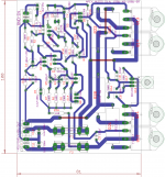
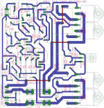
Pl find below apex D14 kelvin amp pcb with TIP141/142. Supply voltage +/-45V. rest of the components and their values are as per original apex layout. would you be kind enough to tell me if there are any errors?
regards
prasi
PS: I have made a larger pcb (100x81 versus original 82.5x62.5) as my soldering skills are awful and dont want to short different pads/tracks.
Attachments
Last edited:
Hi Sonal,
Pl find below apex D14 kelvin amp pcb with TIP141/142. Supply voltage +/-45V. rest of the components and their values are as per original apex layout. would you be kind enough to tell me if there are any errors?
regards
prasi
PS: I have made a larger pcb (100x81 versus original 82.5x62.5) as my soldering skills are awful and dont want to short different pads/tracks.
Hi,
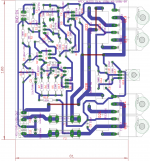
made Small corrections in routing one /two unrouted wires.
PCB attached.
reg
prasi
Attachments
Hi,
made Small corrections in routing one /two unrouted wires.
PCB attached.
reg
prasi
Nice work,
Regards
Hi Sonal,
Pl find below apex D14 kelvin amp pcb with TIP141/142. Supply voltage +/-45V. rest of the components and their values are as per original apex layout. would you be kind enough to tell me if there are any errors?
regards
prasi
PS: I have made a larger pcb (100x81 versus original 82.5x62.5) as my soldering skills are awful and dont want to short different pads/tracks.
Hi Prasi, use 10R/1W resistor to connect power ground to signal ground parallel with 100nF capacitor. Look at image posted, I have used it on all of my Apex NX and AX series amps I have made.
There is lots of space on pcb, add zobel to output of amp. Use 4R7/2W in series with 100nF capacitor.
Regards,
Sonal
Attachments
Last edited:
Hi Prasi, use 10R/1W resistor to connect power ground to signal ground parallel with 100nF capacitor. Look at image posted, I have used it on all of my Apex NX and AX series amps I have made.
There is lots of space on pcb, add zobel to output of amp. Use 4R7/2W in series with 100nF capacitor.
Regards,
Sonal
Hi Sonal,
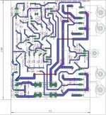
Thanks for your reply and inputs. I have modified the board accordingly and attaching the PCB. I have connected the zobel across amp output and gnd.
reg
prasi
Attachments
Nice work,
Regards
Dear Mile sir,
Thanks for the compliments!. Do you have any comments on the revised PCB attached with Post # 286 which includes a zobel on the o/p and parallel cap and res between signal ground and supply ground?
reg
prasi
Hi sonal awaiting your reply on the modified layout before I buy components and etch the PCB.Hi Prasi, use 10R/1W resistor to connect power ground to signal ground parallel with 100nF capacitor. Look at image posted, I have used it on all of my Apex NX and AX series amps I have made.
There is lots of space on pcb, add zobel to output of amp. Use 4R7/2W in series with 100nF capacitor.
Regards,
Sonal
Reg
Prasi
Hi Prasi, layout is ok, but pad size of resistors, capacitors and some transistors is small for hand drilling. Use any one of eagles design rules files I am posting or edit design rules as you like.
Regards
Sonal
Hi Sonal,
Thanks for DRU file. I checked my PCB with sparkfun.dru and no errors. However, as suggested by you I will go with larger pad sizes for all res/cap/power res/transistors.
thanks again.
reg
prasi
Hi Prasi,
I also lived in Pune. I had made this amp with TIP. U can connect me for any assistance.
Regards
Anjan
Hi Anjan,
thanks for extending your assistance. I am currently occupied with building a diy apex gainclone amp and tone control. when i start building D14 amp i will get in touch with you.
Hi Sonal,
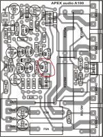
Have a doubt in the layout prepared by me and the amp photo attached by Apex (post no.31, http://www.diyaudio.com/forums/solid-state/163159-150w-mosfet-amplifier-irfp250x2-4.html).
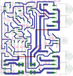
I have made the PCB layout as per schhematic of apex , but Orientation of Q6 BC557 is reversed on the photograph posted by APEX in the above link.
can you confirm, which is correct?
I have attached pics of both circling the difference.
regards
prasi
Have a doubt in the layout prepared by me and the amp photo attached by Apex (post no.31, http://www.diyaudio.com/forums/solid-state/163159-150w-mosfet-amplifier-irfp250x2-4.html).
I have made the PCB layout as per schhematic of apex , but Orientation of Q6 BC557 is reversed on the photograph posted by APEX in the above link.
can you confirm, which is correct?
I have attached pics of both circling the difference.
regards
prasi
Attachments
Last edited:
Hi prasi,
Apex one is correct. I think orientation of BC557 in eagle is wrong, collector should connect to negative supply.
Regards,
Sonal
Hi Sonal and others,
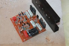
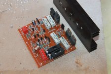
i am attaching herewith my apex kelvin amplifier build . i just need clarification on the MJE350 and MJE340 orientation. whether i havemounted correctly?
As suggested by you earlier, the power ground and signal ground are seperated and also a zobel is incorporated on the amp pcb itself.
reg
prasi
Attachments
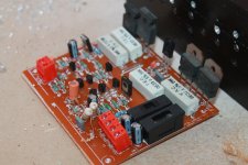
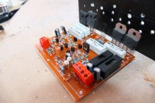
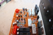
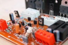
Hi prasi,
MJE350 and MJE340 orientation are ok but heat sink is small for this amplifier. You should check http://diycomponents.in, http://diyaudiocart.com and http://www.gajsupply.com for heat sink.
Regards,
Sonal Kunal
MJE350 and MJE340 orientation are ok but heat sink is small for this amplifier. You should check http://diycomponents.in, http://diyaudiocart.com and http://www.gajsupply.com for heat sink.
Regards,
Sonal Kunal
Hi Sonal,
Thank you for your reply. I have already mounted the pcb on the heatsink that i had. I will just test the amp pcb for its operation and then I will order the new bigger size heat sink as suggested by you from the website. Can I mount both PCB's side by side on a 200-230mm heat sink for stereo application? I am also planning to put a processor fan at the back of amp for extra cooling.
Also kindly answer my following query.
1. How is the bass response of the kelvin amp that you built. I have built the APEX lm3886 and feel that bass is bit lacking ( as compared to SC 301 | astonia audio). Its a soild state amp that has good review on AVmax magazine and sound is amazing , especially the bass. May be they have boosted the bass. Dont know really. May be apex lm3886 is very neutral with a flat frequency response approaching true hi-fi (whats recorded is what should be heard)
reg
prasi
- Home
- Amplifiers
- Solid State
- 150W MOSFET Amplifier with IRFP250x2