Its works, with 50v dc & 20mv bias(for test). I will push bias more higher again.
Many thanks to mr. Mile for schematic & sonal kunal for pcb design.
Please advice for optimmum bias & voltage.
How many watt can deliver from this amp, with 3pair irfp260n, datasheet say 300watt dissipation?
Thanks
Regards

Many thanks to mr. Mile for schematic & sonal kunal for pcb design.
Please advice for optimmum bias & voltage.
How many watt can deliver from this amp, with 3pair irfp260n, datasheet say 300watt dissipation?
Thanks
Regards
Its works, with 50v dc & 20mv bias(for test). I will push bias more higher again.
Many thanks to mr. Mile for schematic & sonal kunal for pcb design.
Please advice for optimmum bias & voltage.
How many watt can deliver from this amp, with 3pair irfp260n, datasheet say 300watt dissipation?
Thanks
Regards
View attachment 468323
Nice work, about 300W/4R with +/-75V
Regards
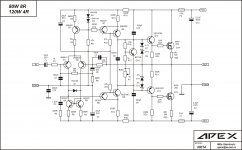
It's a working amplifier,so it's time for pcb posting!Update!! Use +-56volt DC, bias 35mv. No hum, noise, & simple powerfull amp. I use this amp to handle 10" 350watt 2ohm speaker.
Mr. Mile, Can i use 2sd600/D600K instead BD139?(many fake BD series in here)
Thanks
Regard
")
Update!! Use +-56volt DC, bias 35mv. No hum, noise, & simple powerfull amp. I use this amp to handle 10" 350watt 2ohm speaker.
Mr. Mile, Can i use 2sd600/D600K instead BD139?(many fake BD series in here)
Thanks
Regard
Yes many TO126 transistors can be use instead BD139... 2SD669, MJE340...
Regards
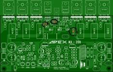
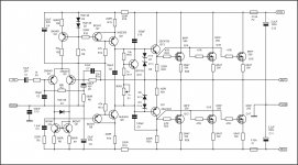
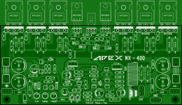
PCB NX-400
Many thanx to Sunal Kunal, he was made this.
Thanks
Regard
It's a working amplifier,so it's time for pcb posting!
Many thanx to Sunal Kunal, he was made this.
Thanks
Regard
Attachments


Last edited:
Mr Miles, i want to ask max value for C4 & C5, can it change with 47uf? i want to build second Nx-400, but my stock 22uf is empty.
Thanks
Regards
Use any value over 22uF
Regards
Nice work thole,  amp is able to drive 2ohm load at 56v.
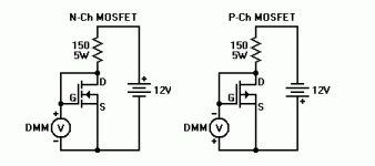
BD139, BD140 fakes, I only buy CDIL make BD139, BD140 other manufacturer marking ones are mostly fake here. Still have few pairs of grey Philips ones.
All files for building this amp.
amp is able to drive 2ohm load at 56v. BD139, BD140 fakes, I only buy CDIL make BD139, BD140 other manufacturer marking ones are mostly fake here. Still have few pairs of grey Philips ones.
All files for building this amp.
Attachments
Last edited:
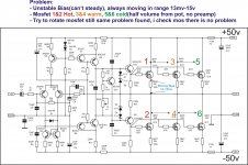
R3 10K in schematic is labeled 22K on layout . Those who downloaded sprint layout file can edit it.
Corrected pdf files.
. Those who downloaded sprint layout file can edit it.Corrected pdf files.
Attachments

- Home
- Amplifiers
- Solid State
- 150W MOSFET Amplifier with IRFP250x2