cathode choke operating point
Tim,
The reason I changed the operating point is because when I inserted the choke and set Rk to exactly the same value it was before, I have a 1k 10 turn pot for that resistance, the distortion level was something like 20dB higher at 1W. Since the purpose of the choke was to improve balance which should lower distortion I would call the first phase of the experiment a failure, so I moved on to the second which was reminimizing distortion.
If you can explain why it went up I would be happy to listen.
By the way, tubecad says I should have 88V of swing at the new operating point and I need 31 to drive the 12B4 grid to zero.
My goals when I started this design as a universal volt amp and driver circuit were to 1) have a large linear swing available from the plate of the 12B4 2) have minimum distortion as the driver stage 3) have minimum parts count 4) operate from a max B+ of 310V.
Following these dicta, when I found out the decoupling capacitor between the plate circuit choke and a)cathode of 6SN7 b)star ground increased distortion level, increased parts count and did not increase voltage swing I chucked it. When I replaced the plate circuit choke with an equal value resistor the same results were shown save parts count remained the same. I kept it. I wish I knew what was happening in that 6SN7 circuit. I can only surmise that as unbalanced AC currents flow through the low valued plate resistor they encounter an enforcer in the form of the 75H choke which adjusts the voltage to rebalance the tubes output. Sense?
Michael
PS: Is -60dB distortion high for a non-global feedback circuit? I can find very little information on this point.
Tim,
For a fair comparison the operating points should be the exact same.
The reason I changed the operating point is because when I inserted the choke and set Rk to exactly the same value it was before, I have a 1k 10 turn pot for that resistance, the distortion level was something like 20dB higher at 1W. Since the purpose of the choke was to improve balance which should lower distortion I would call the first phase of the experiment a failure, so I moved on to the second which was reminimizing distortion.
If you can explain why it went up I would be happy to listen.
By the way, tubecad says I should have 88V of swing at the new operating point and I need 31 to drive the 12B4 grid to zero.
My goals when I started this design as a universal volt amp and driver circuit were to 1) have a large linear swing available from the plate of the 12B4 2) have minimum distortion as the driver stage 3) have minimum parts count 4) operate from a max B+ of 310V.
Following these dicta, when I found out the decoupling capacitor between the plate circuit choke and a)cathode of 6SN7 b)star ground increased distortion level, increased parts count and did not increase voltage swing I chucked it. When I replaced the plate circuit choke with an equal value resistor the same results were shown save parts count remained the same. I kept it. I wish I knew what was happening in that 6SN7 circuit. I can only surmise that as unbalanced AC currents flow through the low valued plate resistor they encounter an enforcer in the form of the 75H choke which adjusts the voltage to rebalance the tubes output. Sense?
Michael
PS: Is -60dB distortion high for a non-global feedback circuit? I can find very little information on this point.
-10dB would be 10% THD, so -20dB (not dBV, remember the distinction!) should be practically inaudiable at full output. Most tube amps are this way (ZNFB triode amps are more like 5%, mostly even).
I don't see why distortion would go up so much, it's impossible as far as I see. This is a built circuit, right?
It's impossible for the circuit to drive the 12B4s properly, since even if there is no voltage drop across the 75H choke, yet the 6SN7s at 211V, that's 48V across the plate resistors - the 6SN7 would have to be almost completely cut off to provide the positive peak (it's already in the nonlinear low current area), and likely wouldn't provide the drive, at least very linearly.
It can't be the 75H acting as a plate choke since the effect would be seen on both tubes, that is, a common mode effect, and rejected by the OPT. I have no idea why you are getting what you see
Tim
listening as I write
Yeah, it's a built circuit. I do wish I had the gumption to learn how to model though. In any case, it is now put back the way it was yesterday, ie no choke in the cathode circuit. Far superior sound. I agree it could only swing 48V with the choke, that is enough to drive the 12B4 though right? As for non-linear, I would say the large increase in 2nd was the proof in the pudding there.
I am not saying the 75H choke is acting as a plate choke, but rather as a CCS. If one section of the 6SN7 is increasing it's current flow more than the other section is decreasing it's flow that would lead to an net changing current through the pair of plate resistors. Is that correct? Since the only places AC plate current can go are through the coupling capacitor and 470k grid leak resistors or through the 22k plate resistors my thought is it mostly goes through the plate resistors. Then if there is a net change in current, it encounters the large choke and the choke causes the supply voltage to change forcing the pair back into balance?
As I may have mentioned, I am out of my league in trying to explain this. The choke started life in the design in the rather more mundane role of power supply filter, but it has proven empirically to play a large role in minimizing distortion levels. I am just trying to figure out the how and why.
Michael
Re: listening as I write
I wish I had the greenbacks to model a distortion analyzer
(Yeah yeah, use the sound card... I should try that some time.)
Yes, this is how a LTP works. Only two differences between that and this is they typically use CCS's, which function down to DC, whereas a choke has a significant bit of resistance below maybe 5Hz. In the audio band it will have the same effect, however, making little difference in our area of interest.
The other difference is that the CCS is usually placed in the cathode circuit. Now, your circuit balances in a rather crude way - which is *ONLY* possible with tubes because the triode happens to exist, as a matter of fact! Transistors and pentodes have little internal feedback, resulting in a high "plate" resistance, which would result in large corrective supply voltage swings, very easily saturating the stage, causing nastified distortion (Dhaen, if you're still reading, that's exactly what I meant by "nastified" above") ). However, the current in a triode can be affected quite well by changing the plate voltage a bit, so it'll work a bit better, not running out of unbalanced headroom as easily. But in both cases, if the CCS is put in the cathode circuit, its effect is amplified by the voltage gain of the tube, resulting in mere volts spent balancing it instead of maybe a hundred volts!
). However, the current in a triode can be affected quite well by changing the plate voltage a bit, so it'll work a bit better, not running out of unbalanced headroom as easily. But in both cases, if the CCS is put in the cathode circuit, its effect is amplified by the voltage gain of the tube, resulting in mere volts spent balancing it instead of maybe a hundred volts!
I'm as as you 
Tim
audiobot said:Yeah, it's a built circuit. I do wish I had the gumption to learn how to model though.
I wish I had the greenbacks to model a distortion analyzer
(Yeah yeah, use the sound card... I should try that some time.)
I am not saying the 75H choke is acting as a plate choke, but rather as a CCS. If one section of the 6SN7 is increasing it's current flow more than the other section is decreasing it's flow that would lead to an net changing current through the pair of plate resistors. Is that correct? Since the only places AC plate current can go are through the coupling capacitor and 470k grid leak resistors or through the 22k plate resistors my thought is it mostly goes through the plate resistors. Then if there is a net change in current, it encounters the large choke and the choke causes the supply voltage to change forcing the pair back into balance?
Yes, this is how a LTP works. Only two differences between that and this is they typically use CCS's, which function down to DC, whereas a choke has a significant bit of resistance below maybe 5Hz. In the audio band it will have the same effect, however, making little difference in our area of interest.
The other difference is that the CCS is usually placed in the cathode circuit. Now, your circuit balances in a rather crude way - which is *ONLY* possible with tubes because the triode happens to exist, as a matter of fact! Transistors and pentodes have little internal feedback, resulting in a high "plate" resistance, which would result in large corrective supply voltage swings, very easily saturating the stage, causing nastified distortion (Dhaen, if you're still reading, that's exactly what I meant by "nastified" above
). However, the current in a triode can be affected quite well by changing the plate voltage a bit, so it'll work a bit better, not running out of unbalanced headroom as easily. But in both cases, if the CCS is put in the cathode circuit, its effect is amplified by the voltage gain of the tube, resulting in mere volts spent balancing it instead of maybe a hundred volts!As I may have mentioned, I am out of my league in trying to explain this. The choke started life in the design in the rather more mundane role of power supply filter, but it has proven empirically to play a large role in minimizing distortion levels. I am just trying to figure out the how and why.
I'm as
as you Tim
Other Ideas?
Anyone else care to jump in here with explanations or theories as to how this circuit behaves? If someone would want to model it I could provide more exact parameters.
What else am I supposed to design for? Good Sound? Kidding!!! I listen to the setup at all of my waypoints, in fact I have barely had my main system on for a month, save for movies and the occasional ear recalibration.
Some comments on the design procedure: I have a variable voltage power supply and rheostats in the cathode circuits of the 6SN7 and 12B4 with an additional balance pot on the 6SN7. After I make a circuit change I use a sort of random walk method of finding an operating point that gives minimum 3rd order distortion. I do this by varying the rheostats at a given power level and finding a minimum. Then I check second order, adjust the balance pot and readjust the rheostats to see what the effect is. If neutral, I change the output level and iterate. When that has yielded a stable, low distortion operating point I vary the B+. Listen. Repeat. Listen. Repeat. If it seems like a good point is found I do a complete distortion vs power output profile.
Some operating points are very twitchy, small changes in one or more parameters lead to large changes in distortion or large drops in linear swing on the plates of the 12B4. I discard those as being impossible to maintain in a real circuit due to aging variation in components or powerline fluctuations. Some are very stable and virtually immune to large changes in all of the parameter values. These I give serious listening time to because I feel they could be used in an amp that would be stable for many years once built.
I know I could do loadline analysis or model this stuff, and I did before it was built, but that wouldn't tell me how it actually sounds. Now in the time it takes me to draw a new loadline on a datasheet and calculate swing voltage and distortion, etc. I can actually be listening to the circuit and that would be the proof in my pudding.
I also know that what I am measuring is not the end all of the circuit. After I put the choke in the cathode circuit yesterday I found a point that measured pretty well. When I got a chance to kick the volume up a little and was listening to some George Winston, ie close miked grand piano with lots of ringy overtones, something was clearly wrong in the higher frequencies. Outcome: restore to last known good point and consider the options (while listening to tasty music).
I do wish I could figure out and explain, to myself at least, what the role of that 75H choke is.
Michael
Anyone else care to jump in here with explanations or theories as to how this circuit behaves? If someone would want to model it I could provide more exact parameters.
BTW I don't know anyone who designs experimentally based on measured distortion - it's not like you're trying to get an exact figure. Just because distortion is low doesn't mean it's working right. (But that statement just doesn't sound right )
What else am I supposed to design for? Good Sound? Kidding!!! I listen to the setup at all of my waypoints, in fact I have barely had my main system on for a month, save for movies and the occasional ear recalibration.
Some comments on the design procedure: I have a variable voltage power supply and rheostats in the cathode circuits of the 6SN7 and 12B4 with an additional balance pot on the 6SN7. After I make a circuit change I use a sort of random walk method of finding an operating point that gives minimum 3rd order distortion. I do this by varying the rheostats at a given power level and finding a minimum. Then I check second order, adjust the balance pot and readjust the rheostats to see what the effect is. If neutral, I change the output level and iterate. When that has yielded a stable, low distortion operating point I vary the B+. Listen. Repeat. Listen. Repeat. If it seems like a good point is found I do a complete distortion vs power output profile.
Some operating points are very twitchy, small changes in one or more parameters lead to large changes in distortion or large drops in linear swing on the plates of the 12B4. I discard those as being impossible to maintain in a real circuit due to aging variation in components or powerline fluctuations. Some are very stable and virtually immune to large changes in all of the parameter values. These I give serious listening time to because I feel they could be used in an amp that would be stable for many years once built.
I know I could do loadline analysis or model this stuff, and I did before it was built, but that wouldn't tell me how it actually sounds. Now in the time it takes me to draw a new loadline on a datasheet and calculate swing voltage and distortion, etc. I can actually be listening to the circuit and that would be the proof in my pudding.
I also know that what I am measuring is not the end all of the circuit. After I put the choke in the cathode circuit yesterday I found a point that measured pretty well. When I got a chance to kick the volume up a little and was listening to some George Winston, ie close miked grand piano with lots of ringy overtones, something was clearly wrong in the higher frequencies. Outcome: restore to last known good point and consider the options (while listening to tasty music).
I do wish I could figure out and explain, to myself at least, what the role of that 75H choke is.
Michael
couple more experiments
Hey,
Did a couple more experiments this morning. First, I rigged up a negative 250V supply. Then I took the 75H choke out of the plate circuit of the 6SN7 and put it into the cathode circuit, along with changing the 1k pot to a 100k. Messed about a little and did some listening. I wasn't overly impressed. When I tried to minimize distortion I had to go into the very low current region again. After that I put the 75H back in the plate circuit, but left the negative supply attached. That sounds a lot better again, still I have to go to low current to get anywhere near ballpark distortion numbers to what I had without the supply. Both setups actually give me distortion numbers somewhat similar to what I had when I tried a 10k Rp +75H choke on the SN7. That setup also sounded quite good, although I think I prefer the 22k Rp a little.
Anyway, there seems to be something about that choke in the plate circuit that just opens up the sound and spreads the intruments out. Remember I am not talking stereo here, so what I mean is that the instruments each seem to maintain their own tonal seperateness. Anyone have any ideas how it does it?
The negative supply does complicate matters and it adds a lot of noise, so I can see to implement properly would be something of a pain. The one I have can't do the current to try it on the 12B4, so maybe later. Maybe not worth it though?
Miles' "Kind of Blue" very much lived up to it's name this morning.
Michael
Well...ears respond to differential phase and amplitude among other things, so it could be affecting the phase and frequency response. A combination of that and reflections in the room (and probably some psychoacoustics of course) could account for what you're hearing.
What's it do when you have no common-mode chokes, that is, replacing the 150H (75? as in the first schematic) with a 1k resistor and bypass the node with a PSU cap?
Tim
What's it do when you have no common-mode chokes, that is, replacing the 150H (75? as in the first schematic) with a 1k resistor and bypass the node with a PSU cap?
Tim
no chokes
Tim,
I know I did that experiment early on, but I can't find notes for it. I may not have kept them, which usually means I didn't like it.
I did try a comparison of a 25 uF polypro/oil in between a) 75H choke and top of 6SN7 cathode resistor b)75H choke and star ground and c)no cap. Results showed 2nd harmonic measured as a)28mV b)56mV c)16mV with 8.4, 8.4 and 8.2 volts output (16R load) for the three setups. Third harmonic was a)116mV b)173mV c)46mV. Above that order there was no measurable affect. I don't have listening notes, but I did remove the cap from the circuit, so I'm guessing...
Doing my weekend cooking now, but will try replacing the choke with a 2.25k resistor and 55uF cap later and see how it sounds.
It is also interesting, to me at least, that there seems to be two "kinds" of second harmonic distortion. If the one is present I can null it out almost completely and it is a minor distortion component at every output level. If it is the other, I can affect it's level somewhat through nulling, but it will be the major distortion component at all levels until clipping. Rather SET like and I am loss to explain it.
Michael
no speaker
Tim,
I am testing this amp with up to 5W output at 1kHz. Would you have a speaker attached? My ears would hurt to much. I use a 16 ohm resistor on the 16 ohm tap, ie the whole secondary winding.
I am not sure I understand you last post completely.
There is definitely transformer distortion if you look at the lower frequencies, <50Hz. All in all though I would say it's not doing to bad for a transformer that was probably designed to be used with a lot of feedback. Frequency response is pretty good. Down ~3dB at 20kHz and 1.3dB 20Hz ref 1kHz. Interestingly, the voltage swing on the plates of the 12B4 increases as frequency goes up following the datasheet curve for the A-11 input transformer pretty closely. So the output loss would appear to be wholly in the OPT. Might be a point in the A-11 favor, which is something I thought of when I first saw the datasheet for it. Designed to compensate for the decreasing response of a mic in the upper registers. Could also work with zero feedback amp with suboptimal OPT.
I first noticed the two types of second when I changed the first 6SN7 I was using for a different one with closely matched sections. Second harmonic went down a bunch, which might make me think that if the distortion is integral to the sections it is cancelled, but if it results from a gain mismatch it is not.
Having some problems with internet access today. AAAArgh.
Michael
Hi,
Andy,
Not many people know this but a trioded EL84 is very similar to a 12B4A in characteristics.
So, if it were me, I'd try wiring the EL84s for triode operation and try that out first.
The OPTs' Zprim will likely be a bit of a mismatch but basically all you'll lose is output power.
Cheers,
Andy,
How it would compare with trioded EL84s I don't know.
Not many people know this but a trioded EL84 is very similar to a 12B4A in characteristics.
So, if it were me, I'd try wiring the EL84s for triode operation and try that out first.
The OPTs' Zprim will likely be a bit of a mismatch but basically all you'll lose is output power.
Cheers,
R vs L
Hi all,
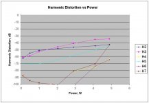
Got around to replacing the 75H choke in the plate circuit with an exactly equivalent R and a 55uF oiler to the star ground. Same DC operating points as in the first analysis. Results of distortion analysis are in the graph below. You might have to look back around page one to compare. Soundwise, it was competent but nothing special was hitting me. May have been because I am in a bad mood from dealing with an ongoing computer problem. I also tried moving the cap to the cathode side of the 6SN7 resistor. Sort of plate to cathode feedback? That resulted in cutting 2nd and 3rd harmonics significantly, as in 30-50%. Noise was about the same as with the choke with a little more emphasis on the lower Hz. After I switched it back to the choke, the first CD struck me the same, but then a Cassandra Wilson CD just really stood out, kind of like what I have been feeling pretty much all the time for the last month. I'm not saying the lower distortion levels are the difference in the sound, but something seems to be doing it different.
Michael
Hi all,
Got around to replacing the 75H choke in the plate circuit with an exactly equivalent R and a 55uF oiler to the star ground. Same DC operating points as in the first analysis. Results of distortion analysis are in the graph below. You might have to look back around page one to compare. Soundwise, it was competent but nothing special was hitting me. May have been because I am in a bad mood from dealing with an ongoing computer problem. I also tried moving the cap to the cathode side of the 6SN7 resistor. Sort of plate to cathode feedback? That resulted in cutting 2nd and 3rd harmonics significantly, as in 30-50%. Noise was about the same as with the choke with a little more emphasis on the lower Hz. After I switched it back to the choke, the first CD struck me the same, but then a Cassandra Wilson CD just really stood out, kind of like what I have been feeling pretty much all the time for the last month. I'm not saying the lower distortion levels are the difference in the sound, but something seems to be doing it different.
Michael
Attachments
Hi,
Michael,
Replacing a choke with the equivalent series resistance of that choke does away with the property of the choke that's the most important here: it's very high AC impedance as seen by the plate.
Comparing both conditions is just the same as comparing apples to oranges.
Hold on...that's a PS choke you replaced, not a plate load choke.
The choke should make an audible difference, certainly a measureable one in your PP design.
Cheers,
PS choke
Right, the choke is in a power supply position. Where as a series element it is neither a low impedance DC supply nor an easy AC path to ground. So why does it make the circuit sound so much clearer and livelier? And why does distortion go down ~10-12dB?
Stumped,
Michael
Right, the choke is in a power supply position. Where as a series element it is neither a low impedance DC supply nor an easy AC path to ground. So why does it make the circuit sound so much clearer and livelier? And why does distortion go down ~10-12dB?
Stumped,
Michael
Hi,
The choke provides for some degree of regulation an it also has much better PSR than just a resistor.
All this means that your circuit proper is allowed to work more freely as it is fed from a much cleaner supply.
If you care to make some measurements on residual ripple on the supply line you'll notice that the choke supply is much cleaner.
Cheers,
So why does it make the circuit sound so much clearer and livelier? And why does distortion go down ~10-12dB?
The choke provides for some degree of regulation an it also has much better PSR than just a resistor.
All this means that your circuit proper is allowed to work more freely as it is fed from a much cleaner supply.
If you care to make some measurements on residual ripple on the supply line you'll notice that the choke supply is much cleaner.
Cheers,
Hi Michael, All
This adventure is very intriguing.
I have the suspicion that the particular behavior of your amplifier is due to a phenomenon of third harmonic cancellation caused by intermodulation of the fundamental with its 2nd harm in each of the output tubes.
I have some difficulty to articulate my hypothesis in English but I’ll get it a try with some simplifications.
When the ultrapath capacitor is present the driver works as two separate SE stages( if cathode res bypassed). At the grid of the following tube 2nd harm dist. is present that will be then cancelled owing to the push-pull structure of the output stage.
In case of no capacitors and a choke at the cathode instead, a circular path is created between the two
driver tube and the stage is balanced. AC current is the same ( but opposite in respect to each tube). This interaction between the tubes cancels the 2nd harmonic. Second harmonic of the driver is cancelled before the output stage.
Choke in the anode is less efficient in balancing the circuit ( in dependence of two factors: 1) the mu of the tube (6sn7) and 2) the presence of the grid leakage res.[here however high: 470k]
Furthermore I have some doubt about the balancing function
of the anode choke at all.
So, with the same working conditions, we see three different situations
a) ultrapath present: high 2nd harm. In 12b4a grid
b) cathode choke : low 2nd harm
c) anode choke: intermediate 2nd harm.
I made some simulations to verify this sort of things and they confirm the above statement except that in case c) I found higher 2nd order residuals than in a), but it does not matter.
Well, what happens.
When second harmonic exists it, in combination with the fundamental, generate
an intermodulation distortion of order, among others, f1+f2, which correspond to a third order
harmonic. This intermodulation takes place in the output tubes. A specific amount of 2nd order exists which generate the right amount of 3rd order that will cancel the 3rd order intrinsic of the output tube.
So, with the cathode choke configuration we have no 2nd order from driver, thus no cancellation and
high 3rd order at the output.
Maybe, in case of anode choke, the correct amount of 2nd order is produced and this greatly reduces 3rd order distortion ( and also total harm dist ) at the output. It is a little fortuitous since it will depend on the characteristics of the tubes, both driver and output and on other things. And it has also
When you put the choke in the cathode the 2nd harm decrease ( in 6sn7) so 3rd harm increase at the output and you have to decrease the steady state current ( by increasing the cathode res) to decrease output dist.
Really, by decreasing the current you are going in a worse working point but you does not see this since you see only the decreased output dist. and not the increased 2nd order of the driver stage.
I think it is useful to execute distortion measurements also on the grid of a 12b4a, I mean essentially
2nd order dist. measures.
To confirm my hypothesis, I am now simulating the output stage alone and I utilize, as input, four signal generator, the first two are 1k Hz gen. with opposite polarities. The other two ( in series with the previous) are 2k Hz gen with the same phase to simulate the second order distortion.
I’ll report you the results as soon as possible.
Bye
federico
Most interesting
Federico,
Very interesting hypothesis. I don't know quite how to lay out questions and results for you.
First, would you like me to measure any particular set of circuit layouts and/or operating conditions?
I have measured the distortion present at the grid of the 12B4 once in the past. Unfortunately I did not collect the DC conditions for the test. I am quite sure the choke was present in the anode circuit at the time and I believe there was no capacitor in the 6SN7 portion of the circuit, but the 55uF capacitor from the OPT centertap to the top of the cathode resistor of the 12B4 was present. I have not graphed or drawn a table of this data. If you wish I can do that.
I measured the distortion profile at two different input levels.
The first was such that the overall amplifier output was 4W. By oscilloscope quantitation the voltage swing on the grid of the 12B4 was 64V pk-pk. Measured by HP302A Wave Analyzer, the fundamental was 22Vrms, H2 was 0.76Vrms (3.55%), H3 was 60mV (0.27%) and all other harmonics were <0.05% each. The results were the same for both sections of the 6SN7 except the output level for one measured 0.2V greater than the other, maybe inside of error bar of measurements. At what I believe were nearly the same settings, the voltages at the output transformer secondary (16 ohm load) measured 8.0V for the fundamental, 2mV for H2 (0.025%), 25.5mV for H3 (0.3%) and 16mV for H5 (0.2%).
The second set of measurements on the grid of the 12B4 was at H1=10Vrms, H2=150mV (1.5%), H3=5.5mV (0.055%), H5=3.7mV (0.01%). At this same setting the overall output was 1W and the measurements at the secondary of the OPT were H1=3.8V, H2=1.3mV, H3=3.7mV and H5=1mV.
Is that helpful for your model? As you can see, since I measure the distortions with a wave analyzer it is rather more time consuming than automated software analysis, but I will take other measurements if you wish.
Michael
Hi Michael
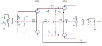
I am actually experimenting with the following
setup.
Note that to have 22V rms at the grid of 12b4a
and 8 at the output I have changed the trafo
and now it is (5.76k:8). May be, the trafo was right
and I have some other differences (tube gain?).
If some value is different, please tell me.
ciao
Federico
Attachments
schematic
Federico,
That looks very close. The DCR of the 75H choke is 2190 ohms. The DCR of the OPT primary sides are 189 and 209 ohms. According to the specifications for the amplifier I removed the OPT from, the impedance is 8.6k.
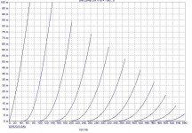
Did you get the curves for the 12B4 from Spice? Very nice in any case.
Michael
Federico,
That looks very close. The DCR of the 75H choke is 2190 ohms. The DCR of the OPT primary sides are 189 and 209 ohms. According to the specifications for the amplifier I removed the OPT from, the impedance is 8.6k.
Did you get the curves for the 12B4 from Spice? Very nice in any case.
Michael
- Status
- This old topic is closed. If you want to reopen this topic, contact a moderator using the "Report Post" button.
- Home
- Amplifiers
- Tubes / Valves
- 12B4A PP schematic