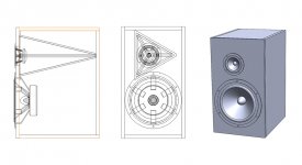
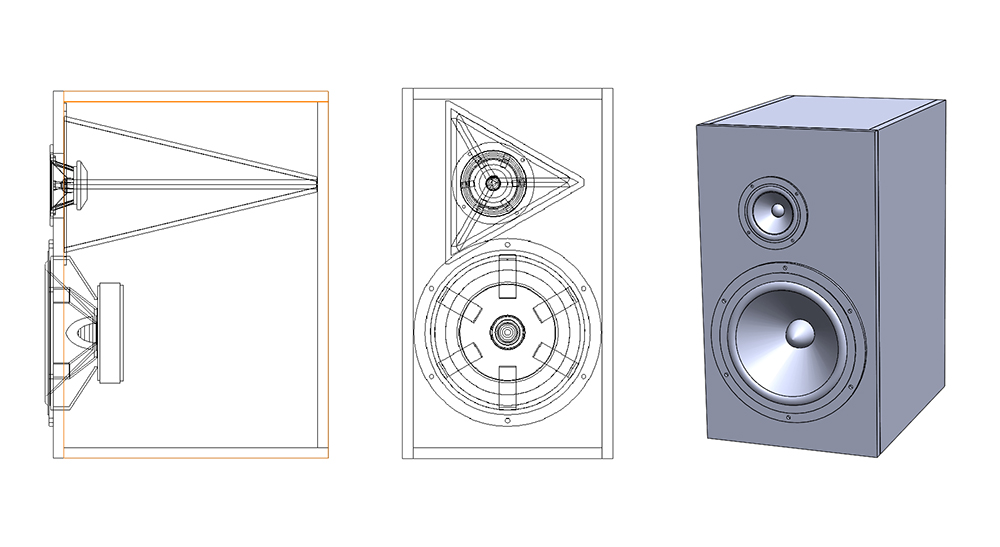
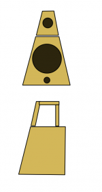
The cabinet is starting to take shape, at least in my mind anyway. Here is the latest take on the "ATC Monitor look". That new XO, btw, rocks hard. I am falling in love with the sound of these speakers all over again and listening to my collection. I can hear new details not heard before. The transient perfect aspect is wonderful for live ambient mic'd recordings.
looks good, I am planning to build this and i was also working on my box sketch :
looking forward to see the how SB acoustic woofer works out.
Attachments
looks good, I am planning to build this and i was also working on my box sketch :

looking forward to see the how SB acoustic woofer works out.
That's awesome! Similar to what I've been planning, but I'm leaving the dagger exposed above the LF box.
thanks, that sounds interesting, gonna work around that idea, will share if i come up with anything.That's awesome! Similar to what I've been planning, but I'm leaving the dagger exposed above the LF box.
looks good, I am planning to build this and i was also working on my box sketch :
looking forward to see the how SB acoustic woofer works out.
Nice work Atto. I didn’t know you do speakers too? Is that an SB 8in in the CAD model? How much of this will be made with your CNC laser cutter?
Don’t forget to flip upside down for woofer on top to be transient perfect or else a 3in steppes baffle needed to set back 10F.
Don’t forget to flip upside down for woofer on top to be transient perfect or else a 3in steppes baffle needed to set back 10F.
Doesn't there need to be a certain listening distance where this is true or am I over thinking it?
Strictly speaking, there is only one axis where the distance difference between the two driver centerlines will always be 3in. When offset is done with stepped baffle, it’s the tweeter axis. When flipping speaker upside down, it just happens to be close to the diagonal projected from 10F up to the listener ears assuming speaker is on suitably high 30in stand. When you get back to 3m away it’s less important but the small difference still helps to move the tweeter rising edge to match where the woofer acoustic center is (recessed into the speaker cabinet). Only in a coaxial synergy born style speaker will the delay always be consistent everywhere. Or with a DSP delayed coaxial woofer/tweeter.
However, in all cases, the step response will be markedly superior from standpoint of producing a right triangle response shape that represents the ideal transient perfect speaker.
However, in all cases, the step response will be markedly superior from standpoint of producing a right triangle response shape that represents the ideal transient perfect speaker.
Last edited:
Nice work Atto. I didn’t know you do speakers too? Is that an SB 8in in the CAD model? How much of this will be made with your CNC laser cutter?
Don’t forget to flip upside down for woofer on top to be transient perfect or else a 3in steppes baffle needed to set back 10F.
thanks, i did designed some in the past years ago.
the speaker is Dayton, but i ll probably go for SB, i was thinking to use a mark audio for HF and a SB woofer but i like your combination better..
3in stepped baffle is not as easy to build, i m thinking of maybe combining pcgab idea of having HF separated on top combined with a LF section, i have to work on it see if i can come up with something , was thinking something like this with HF section 3" back.
Attachments
Last edited:
The 3in stepped baffle also looks very unconventional and doesn't fit a rectangular prismatic box. So that was why I cheated and flipped it upside down. It really works for some strange reason. All you have to do is look at an 8in woofer and estimate where the voice coil physically sits, now the wideband's voice coil needs to be at about the same position axially. There is no way to do that easily - other than do what you show above or what Pcgab did with two separate boxes.
Is that your speaker that you designed years back, Atto?
Is that your speaker that you designed years back, Atto?
The 3in stepped baffle also looks very unconventional and doesn't fit a rectangular prismatic box. So that was why I cheated and flipped it upside down. It really works for some strange reason. All you have to do is look at an 8in woofer and estimate where the voice coil physically sits, now the wideband's voice coil needs to be at about the same position axially. There is no way to do that easily - other than do what you show above or what Pcgab did with two separate boxes.
Is that your speaker that you designed years back, Atto?
oh no, this is out of my price range, lol.
i built a guitar speaker/amp combo for a friend of mine a bass guitar cab, a full range cab, and a cab with car speakers ! it was like 15 years ago i guess.
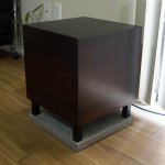
i was out of audio scene for a long long time, came back like a year ago, this is my first recent built , 8in dayton sub with concrete base:
btw you asked if it's gonna be laser cut, no my laser cutter is only 40w will barely cut through 1/4 plywood, also it is only 8 by 10 inches , it would be all hand power, no router no table saw no power toolsxrk971 said:How much of this will be made with your CNC laser cutter?
.

Attachments
Last edited:
A pair of SB23NRXS45-8’s are on their way to my lab.
Exciting in it has very good reputation, for a 1st order crossed system using curves from manufactures datasheets it looks you got some new work to do into Xsim but lets see when in feels its new baffle geometry
Attachments
The 3in stepped baffle also looks very unconventional and doesn't fit a rectangular prismatic box. So that was why I cheated and flipped it upside down. It really works for some strange reason.
I found this explanation by Jeff Bagby (Jeff B) Tweeter on the Bottom - Techtalk Speaker Building, Audio, Video Discussion Forum
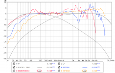
Graph is traced from original datasheet and tool is free FPGraph tracer from here FPGraphTracer : fprawn labs, a tip is if datasheet has too many traces into same graph so trace program gets confused and mix them up then start in MS paint and erase nearby traces so that they don't interfer. To also get phase calculated use either a Jeff Bagby tool or in Xsim open driver window and use "derived" feature and then export, you can trace zma files in the same way, below is attached my response tracing including phase extraction. To keep passive component numbers low X finger that datasheet 5dB response change around 1kHz area will not show up when it feels its new baffle .
.Attachments
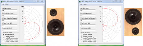
Only guessing here but with enclosure turned 180º around tweeter sits some degree off axis relative to design axis and mayby more near to green trace from datasheet, then comes woofer is expected to be only 20dB down one decade above XO point frq and can it keep that, then in situation baffle step and diffraction effects and also the strange vertical tilted lobe or nulling as 1st order out of phase slopes develop is probably relative sensitive to microphone height as seen in XDir simulation with estimated numbers for XO frq and ctc distance.
Attachments
Last edited:
- Home
- Loudspeakers
- Full Range
- 10F/8424 & RS225-8 FAST / WAW Ref Monitor