sorry!but topic is verry long!I cant find it!
You can thanks nazirdigi for pdf
You can thanks nazirdigi for pdf
i dont find the thanks????
i dont find the thanks????
Go to post #1240
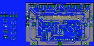
Hi Apex,
Is c10 and r29 in parallel?will there be no problem if I connected d7 and d8 in supply and output.I noticed in your schematic it is in series with resistor emitter.
regards,
joel
Yes c10 and r29 is in parallel, and no problem to connected d7 and d8 in supply and output.
Replace C6 with 1000uF/16V instead 100uF.
Regards
Last edited:
thanks apex for the reply.
enjoy
regards,
joel
Nice design,
regards
thanks apex for the reply.
enjoy
regards,
joel
thanks your share
are you test??
thanks drowranger
What is voltage supply for this amplifier,and what power it is?
Thanks for the files,great job!
thanks apex for the reply.
enjoy
regards,
joel
What is voltage supply for this amplifier,and what power it is?
Thanks for the files,great job!
What is voltage supply for this amplifier,and what power it is?
Thanks for the files,great job!
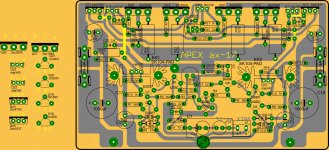
Rail voltage for AX17 is +/-45V
take a look at...
http://www.diyaudio.com/forums/soli...imate-fidelity-amplifier-123.html#post2948259
can you post pcb of the VU meter of post #182 or post #1224?
http://www.diyaudio.com/forums/soli...imate-fidelity-amplifier-123.html#post2948259
can you post pcb of the VU meter of post #182 or post #1224?
But there is pcb in post #1224
Just finished putting together AX17 as per post 1248. Replaced R13 with 2k pot to adjust DC offset to 0V. It works but for some reason can't adjust bias above 13ma (130mV across 10R instead of fuses) and Vbe on BD139 only 0.66V??? Checked everything twice and can't figure it out. Any ideas?
- Home
- Amplifiers
- Solid State
- 100W Ultimate Fidelity Amplifier