dc offset
first of all if you have a problem with dc offset first thing you should check is the differential transistor and the current sources and tail current.the potentiometer is responsible for dc bias if you change value you will have problem with getting the ideal bias voltage.compare my schematics with apex .when my schematic is wrong my layout also.check also resistor value and capacitor polarity.check polarity of c6 and compare to apex schematic.i think eventhough its wrong polarity it will not cause trouble.i dont have apex schematics right now so i cannot compare. And also make sure the gnd is connected to chassis along with the power supply gnd.
first of all if you have a problem with dc offset first thing you should check is the differential transistor and the current sources and tail current.the potentiometer is responsible for dc bias if you change value you will have problem with getting the ideal bias voltage.compare my schematics with apex .when my schematic is wrong my layout also.check also resistor value and capacitor polarity.check polarity of c6 and compare to apex schematic.i think eventhough its wrong polarity it will not cause trouble.i dont have apex schematics right now so i cannot compare. And also make sure the gnd is connected to chassis along with the power supply gnd.
What the resistor value you use on the base-colector of VBE?Just finished putting together AX17 as per post 1248. Replaced R13 with 2k pot to adjust DC offset to 0V. It works but for some reason can't adjust bias above 13ma (130mV across 10R instead of fuses) and Vbe on BD139 only 0.66V??? Checked everything twice and can't figure it out. Any ideas?
I was have same problem, maybe you can try this
I use 1k2 & workingReplace R21 (1k) with 1,2k or 1,5k and you can set 15mV across 0,33R.
")
R22(base-emiter) on my AX17 is 220R & I bypass P1(bias) for 100mA bias
With that higher resistor value you can easily get more bias on output
Regards
Last edited:
I use PCB from post 1023, that was "hand made" PCB...
& there is little mistake on that PCB...
attachment post 1140 is the correct lay out.
You must use ExpressPCB to open the file.
"there is AX 17 TO.gif & not matched to the .pcb file"
that my false, I'm sorry to make confuse any other.
I will post picture of AX17 when I fix it C6 & I will use SanKen at output
Regards
Last edited:
John/Joel,
Thanks for the help. I did as you and Mile's suggested and replaced with 1.2k left the trimpot and 220R. Adjusted fine to ca 100ma (30mv on .33R's) for the dual staged amp.
Thanks, JPR
What about sound?
Regards
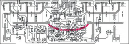
My AX14 by APEX Redraw Jhon BALI
I can not say anymore but I'm holding thumbs for the AX14. with a clear voice and a clear vocal sound. I use the car speakers with a homemade box. APEX and thanks for the layout of the components in the image repeated by John Bali from my country Indonesia.
https://lh4.googleusercontent.com/-...AAAAAAAAxY/HfwEPHVN1cE/s817/Dalimunthe857.jpg
https://lh3.googleusercontent.com/-...AAAAAAAAxg/fpZXwGVgG50/s817/Dalimunthe858.jpg
https://lh4.googleusercontent.com/-...AAAAAAAAxc/TwFcGfqk7RQ/s817/Dalimunthe859.jpg
https://lh4.googleusercontent.com/-...AAAAAAAAxw/nHa8SdEOn9Q/s817/Dalimunthe860.jpg
https://lh6.googleusercontent.com/-...AAAAAAAAx0/VAaS-k85Aao/s817/Dalimunthe862.jpg
https://lh5.googleusercontent.com/-...AAAAAAAAyA/3oV9zr7tAIg/s817/Dalimunthe863.jpg
Lookin´ really good,how does it soud? If it is like NX or simmilar than you have a plenty of power that sounds really good! Yesterday for the first time i have pushed it to the limit and it reached 100W into 8Ohm speakers just like that! No hearing sound distorsion,i wouldn´t know that it was at that power if there was no clip-indication from APEX PSU clip+protection. As i understood it blinks when voltage at speaker reaches PSU - 6V. The PSU voltage is +/- 50.5 V (APEX PSU10) so the Vp was 44V...just like that! With IRFP20 in output it has a little bit more power,but when you cross over 60W than the power is not important,just the sound.
Great job DAMANHURI!
Great job DAMANHURI!
Last edited:
I can not say anymore but I'm holding thumbs for the AX14. with a clear voice and a clear vocal sound. I use the car speakers with a homemade box. APEX and thanks for the layout of the components in the image repeated by John Bali from my country Indonesia.
https://lh4.googleusercontent.com/-...AAAAAAAAxY/HfwEPHVN1cE/s817/Dalimunthe857.jpg
https://lh3.googleusercontent.com/-...AAAAAAAAxg/fpZXwGVgG50/s817/Dalimunthe858.jpg
https://lh4.googleusercontent.com/-...AAAAAAAAxc/TwFcGfqk7RQ/s817/Dalimunthe859.jpg
https://lh4.googleusercontent.com/-...AAAAAAAAxw/nHa8SdEOn9Q/s817/Dalimunthe860.jpg
https://lh6.googleusercontent.com/-...AAAAAAAAx0/VAaS-k85Aao/s817/Dalimunthe862.jpg
https://lh5.googleusercontent.com/-...AAAAAAAAyA/3oV9zr7tAIg/s817/Dalimunthe863.jpg
Nice work
Congratulation Dear Damanhuri...
Terima Kasih Mas Arif.
Thanks Mas Arif
Thanks APEX and 44250.
I enjoy the sound of AX14
Thanks DAMANHURI for shareing pictures of your work, and enjoy in music,
Regards
Hi! Mile
How to improve treble response in ax-14
Why, what's wrong with treble response of AX14? If you want more treble use equliser or preamp with tone controls for bass and treble.
Why, what's wrong with treble response of AX14? If you want more treble use equliser or preamp with tone controls for bass and treble.
feel less treble and more bass in ax-14
may be of fake mje350 and mje 340 ?
if fake mjes are used is there any chances to less hf response?
can i change input capacitor to 0.1uf mylar capacitor for brightness
feel less treble and more bass in ax-14
may be of fake mje350 and mje 340 ?
if fake mjes are used is there any chances to less hf response?
can i change input capacitor to 0.1uf mylar capacitor for brightness
Use 2SA/2SC instead MJEs and try.
Hi! Sir Apex,
It's been a while guess I have lost track of the progress in this thread...
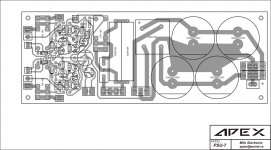
Actually I have been keeping these files for my future DIY project and I guess it's about time...will these pair of circuit work effectively? (below image)
However I may have a problem acquiring BC517, any sub for this transistors?
Also what could be the safe value for T5A (thermistor) in the soft start.?
I assume the protect terminal of the amp connects to the protect terminal of the PSU? Kindly clarify would there be any component changes on both circuit. I will be using +/-50vdc rated at 500w.
Guess I have asked too much
Regards!
It's been a while guess I have lost track of the progress in this thread...
Actually I have been keeping these files for my future DIY project and I guess it's about time...will these pair of circuit work effectively? (below image)
However I may have a problem acquiring BC517, any sub for this transistors?
Also what could be the safe value for T5A (thermistor) in the soft start.?
I assume the protect terminal of the amp connects to the protect terminal of the PSU? Kindly clarify would there be any component changes on both circuit. I will be using +/-50vdc rated at 500w.
Guess I have asked too much
Regards!
Attachments
- Home
- Amplifiers
- Solid State
- 100W Ultimate Fidelity Amplifier